Open Nav



When your circuit board contains Ball Grid Array (BGA) or Quad Flat No-leads (QFN) packages, visual inspection alone cannot guarantee solder joint integrity. Hidden beneath these components, solder defects can lurk undetected until field failures occur. X-ray inspection technology provides the only reliable method for verifying hidden connections, protecting product reliability and customer satisfaction.
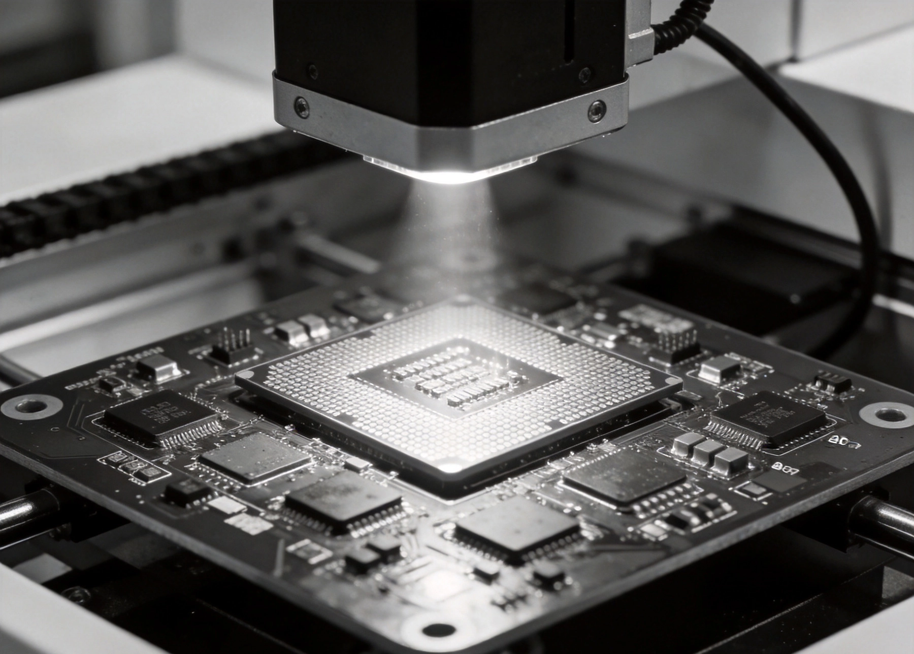
Traditional surface mount components expose their solder joints for easy visual inspection. Gull-wing leads on QFP packages and chip resistors allow technicians to verify solder fillets directly. However, BGA and QFN packages deliberately conceal their interconnections, creating inspection challenges that optical methods cannot address.
BGA packages place solder balls underneath the component body, making every joint invisible from any angle. Even the perimeter balls remain hidden behind the package edge. With ball pitches reaching 0.4mm and diameters approaching 0.2mm, BGAs pack hundreds of connections into compact footprints that power modern electronics.
QFN packages feature thermal pads covering most of the component underside, surrounded by perimeter leads that extend horizontally beneath the package. While leads touch the pads, their solder joints remain partially obscured. The thermal pad's large area makes void detection particularly important for thermal performance.
Without X-ray inspection, manufacturers rely on electrical testing to detect connection failures. However, many solder defects pass electrical tests initially, only failing later due to mechanical stress, thermal cycling, or vibration. Hidden defects create latent reliability risks that manifest as field failures.
X-ray imaging exposes multiple defect types that compromise electrical connectivity, thermal performance, and mechanical reliability. Understanding these defects helps engineers specify appropriate inspection criteria.
Solder bridging occurs when excess solder connects adjacent balls or leads, creating short circuits. In BGA applications, bridges might span only 0.4mm pitch distances, requiring high-resolution X-ray imaging to detect. QFN bridging can occur between closely spaced leads or between leads and the thermal pad.
Solder voids represent gas pockets trapped within solder joints during reflow. While small voids are acceptable, excessive voiding reduces electrical conductivity, thermal transfer, and mechanical strength. IPC standards limit voiding to 25% of joint area for most applications, though thermal pads require stricter limits due to heat dissipation requirements.
Insufficient solder creates weak connections prone to cracking under mechanical stress. X-ray imaging reveals whether solder balls have properly collapsed during reflow, forming adequate joint heights. Insufficient solder on QFN leads reduces contact area and increases resistance.
Missing connections represent complete failures where solder balls failed to contact pads or leads never connected. These defects might result from stencil printing errors, component misplacement, or reflow profile issues.
Head-in-pillow defects occur when BGA balls fail to merge with solder paste during reflow, leaving a visible separation line. This defect allows initial electrical contact but causes failures under thermal cycling as differential expansion stresses the interface.
Joint cracking might appear after assembly due to mechanical stress or thermal shock. X-ray inspection during production can catch existing cracks before products ship.
Modern X-ray inspection systems range from simple 2D imaging to sophisticated computed tomography (CT) scanning. Understanding capabilities helps match technology to application requirements.
2D X-ray inspection provides plan view images showing component positions, ball presence, and obvious bridging. These systems work well for basic defect detection and process monitoring. However, 2D images cannot distinguish overlapping features in dense component arrays or accurately measure void percentages.
2.5D X-ray systems add oblique viewing angles, tilting the X-ray source or detector to capture multiple perspectives. This enables better inspection of ball shape, joint geometry, and void distribution. Operators can rotate images to examine specific areas from different angles.
3D X-ray or laminography captures multiple images at different depths, enabling slice-by-slice inspection. This technology separates overlapping features, allowing accurate void measurement within specific joint volumes. 3D inspection works particularly well for double-sided boards where components on opposite sides create imaging interference.
Computed tomography (CT) provides the most detailed inspection capability, creating full three-dimensional models from hundreds of X-ray projections. CT scanning reveals internal joint structures with micron-level resolution, enabling precise void measurement and defect characterization. However, CT inspection requires longer cycle times and higher equipment investment.
Production environments demand inspection speeds compatible with assembly line throughput. Automated X-ray inspection systems provide consistent, repeatable evaluation without operator fatigue.
Inline AXI systems integrate directly into production lines, inspecting every board or statistical samples based on program requirements. Modern systems achieve inspection rates supporting typical SMT line speeds while maintaining resolution adequate for 0.4mm pitch BGAs.
Offline AXI systems offer higher resolution and flexibility for detailed analysis, first article inspection, and failure analysis. Laboratories use offline systems for process characterization and customer qualification samples.
AXI programming defines inspection regions, defect criteria, and acceptance thresholds. Programs identify component locations from CAD data or teach-mode learning. Programming effort varies with board complexity, requiring optimization for throughput versus coverage trade-offs.
False call rates significantly impact AXI effectiveness. Excessive false rejects waste production time and erode confidence in inspection results. Reliable AXI systems tune detection algorithms to minimize false calls while maintaining true defect capture rates.
X-ray inspection investment should align with defect risk, product requirements, and quality objectives. Strategic implementation maximizes value while controlling costs.
Prototype and first article inspection benefits from comprehensive X-ray analysis. Before committing to production, verify that paste printing, placement, and reflow processes produce acceptable hidden joints. Early defect detection prevents costly production problems.
Process qualification requires statistical sampling of production output to establish baseline defect rates. X-ray inspection data validates process capability and identifies improvement opportunities before ramping to volume.
Production monitoring uses periodic X-ray sampling to detect process drift. Statistical process control methods establish sampling frequencies based on defect probability and production volumes.
High-reliability applications demand 100% X-ray inspection for critical connections. Medical devices, automotive electronics, aerospace systems, and industrial equipment often specify X-ray verification for all hidden joints.
Failure analysis utilizes X-ray inspection to identify root causes of field failures. Non-destructive analysis preserves evidence for subsequent destructive testing if needed.
Effective X-ray inspection programs combine appropriate equipment, trained operators, and disciplined procedures. Following best practices ensures reliable defect detection and consistent quality assurance.
Define acceptance criteria based on IPC standards and application requirements. IPC-A-610 Class 2 allows up to 25% voiding in BGA joints, while Class 3 reduces this to 25% with additional joint quality requirements. Thermal pad voiding limits often specify 30-50% maximum depending on power dissipation needs.
Calibrate inspection parameters to achieve adequate resolution without excessive exposure. Higher X-ray intensity improves image quality but increases radiation exposure to surrounding components. Balance image quality against potential radiation damage to sensitive devices.
Train operators thoroughly on equipment operation, defect recognition, and decision criteria. Certification programs ensure consistent interpretation across shifts and operators. Regular proficiency testing maintains inspection accuracy.
Document inspection results with images and measurement data. Archive inspection records for traceability, supporting customer audits and failure investigations. Modern AXI systems automatically capture digital records linked to board serial numbers.
Correlate X-ray findings with functional test results to validate inspection effectiveness. If functional failures reveal defects X-ray missed, adjust detection parameters. If X-ray rejects pass functional testing, review false call rates.
Not all assembly facilities maintain X-ray inspection capabilities. When selecting manufacturing partners, evaluate X-ray inspection offerings alongside other quality systems.
Equipment capabilities should match your component and board requirements. Verify resolution specifications for your smallest pitch devices. Confirm inspection throughput meets production schedule demands.
Technical expertise ensures inspection programs capture relevant defects. Partner engineers should understand solder joint formation, typical defect mechanisms, and appropriate detection methods for your application.
Reporting and documentation practices affect your ability to demonstrate quality to customers. Request sample inspection reports and verify they contain adequate detail for your quality record requirements.
Cost structures vary based on coverage levels and sampling frequencies. Understand pricing for 100% inspection versus statistical sampling. Factor X-ray inspection costs into total manufacturing economics.
Response times for offline analysis and failure investigation affect development schedules. Establish turnaround expectations for non-routine inspection requests.
X-ray inspection adds cost to assembly processes, but these costs must be weighed against failure consequences. Hidden defect escapes can create expenses far exceeding inspection investment.
Field failure costs include warranty claims, customer dissatisfaction, and potential liability exposure. A single field failure might cost more than X-ray inspection for an entire production lot, depending on product value and customer impact.
Rework costs for hidden defects often exceed initial assembly costs. BGA removal risks board damage, and replacement components add material expense. X-ray inspection before conformal coating or final assembly enables cheaper defect correction.
Quality reputation affects business sustainability. Customers remember reliability problems longer than price competitiveness. X-ray inspection demonstrates commitment to quality that builds lasting relationships.
X-ray inspection provides essential quality assurance for BGA and QFN packages where visual inspection cannot verify solder joint integrity. By revealing hidden defects like bridging, voiding, insufficient solder, and missing connections, X-ray technology prevents latent failures from reaching customers.
Modern X-ray systems offer various capability levels, from basic 2D imaging to sophisticated computed tomography. Matching inspection technology to application requirements optimizes the balance between defect detection and production efficiency. Automated X-ray inspection enables consistent, repeatable evaluation suitable for production environments.
Implementing X-ray inspection strategically during prototype validation, process qualification, and production monitoring establishes quality baselines and detects process drift before defects multiply. High-reliability applications benefit from 100% inspection, while volume production might employ statistical sampling based on defect probability.
When selecting assembly partners, evaluate X-ray inspection capabilities alongside other quality systems. Equipment specifications, technical expertise, and documentation practices determine inspection effectiveness. The investment in X-ray inspection pays dividends through reduced field failures, lower rework costs, and enhanced quality reputation.
X-ray exposure can affect some sensitive components, particularly memory devices and certain semiconductors. However, modern X-ray systems minimize exposure through optimized imaging parameters. Consult component manufacturers' specifications regarding radiation sensitivity and specify acceptable exposure levels when inspection requirements demand extended imaging.
IPC-A-610 standards allow up to 25% voiding for most BGA applications in Class 2 and Class 3 products. However, application-specific requirements might specify tighter limits. High-power devices or thermally demanding applications often require voiding below 20% for optimal thermal performance.
Inspection time varies with board complexity, component count, and inspection coverage. Simple boards might require under one minute for basic inspection. Complex boards with multiple BGA and QFN devices requiring detailed analysis might need 5-10 minutes. Inline AXI systems optimized for production can achieve throughput matching typical assembly line speeds.
X-ray inspection isn't universally required but is highly recommended for applications where hidden joint failures create significant consequences. Medical devices, automotive electronics, aerospace systems, and industrial equipment typically specify X-ray verification. Consumer electronics might rely on functional testing for cost reasons, accepting higher field failure risk.
Yes, X-ray imaging can reveal cracks in solder joints, though crack detection requires higher resolution than void measurement. 3D X-ray or CT scanning provides better crack detection capability than 2D imaging by revealing crack orientation and depth. Surface crack detection might benefit from complementary inspection methods like dye-and-pry analysis.
Reducing Risk in Electronics Manufacturing with Full Turnkey ServicesAugust/15/2026
The Science of Solder Paste Printing: Keys to Perfect SMT AssemblyMay/19/2026
Managing Component Sourcing for Low Volume Production RunsSeptember/26/2026
Choosing the Right Surface Finish for Your SMT PCB AssemblySeptember/23/2026
SMT vs. THT: Understanding the Differences in PCB Assembly TechnologiesMay/19/2026