Open Nav



Every smartphone you hold, every car dashboard that lights up, and every medical device that monitors a patient's vital signs shares a common foundation: PCBA, or Printed Circuit Board Assembly. This technology forms the invisible backbone of virtually all modern electronic devices, transforming raw electronic components into functional circuits that power our connected world.
Despite its ubiquity, PCBA remains misunderstood by many outside the electronics industry. Understanding how PCBA works, why quality matters in the assembly process, and what factors determine manufacturing success helps engineers, product managers, and procurement specialists make better decisions when developing electronic products.
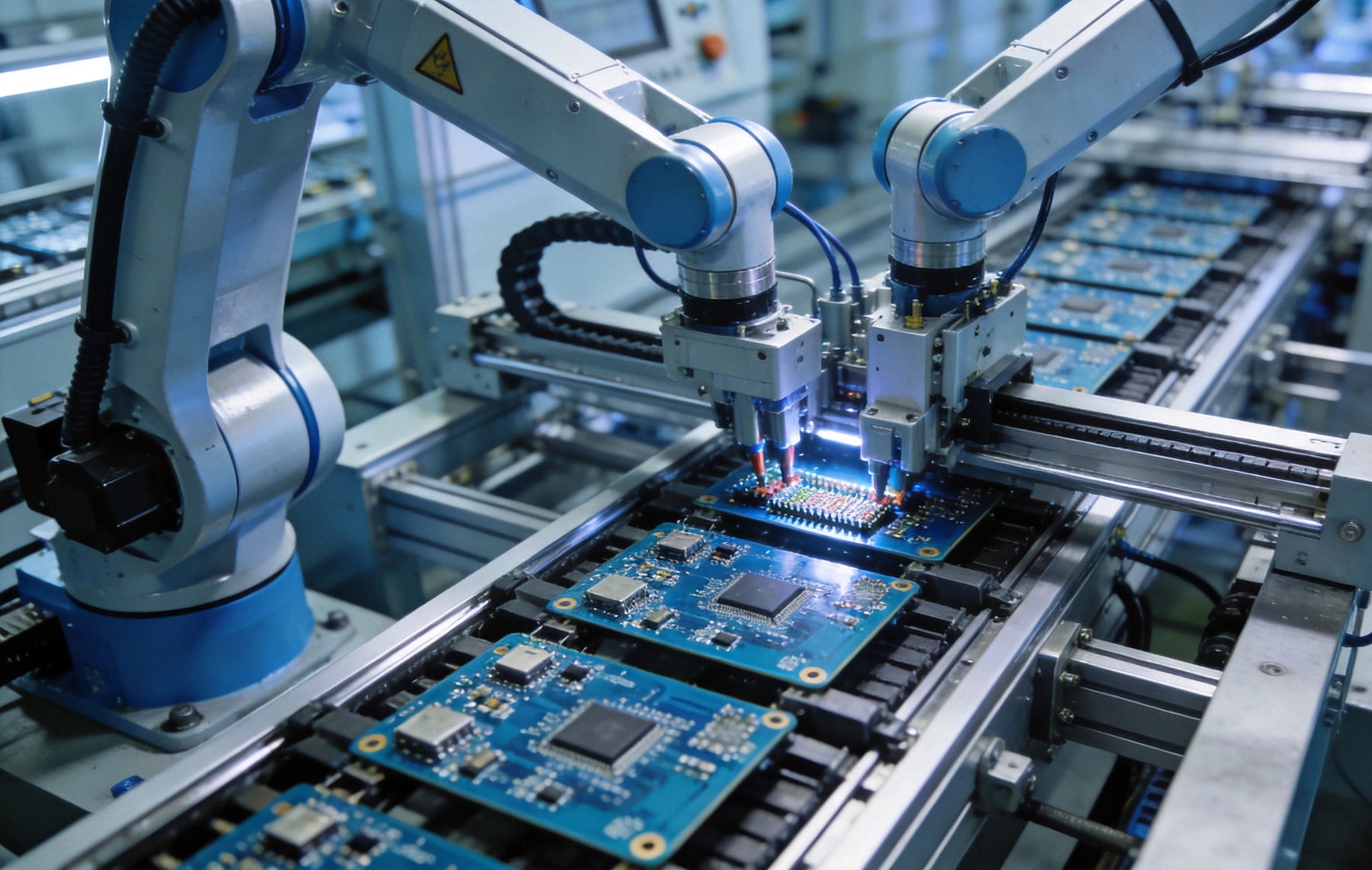
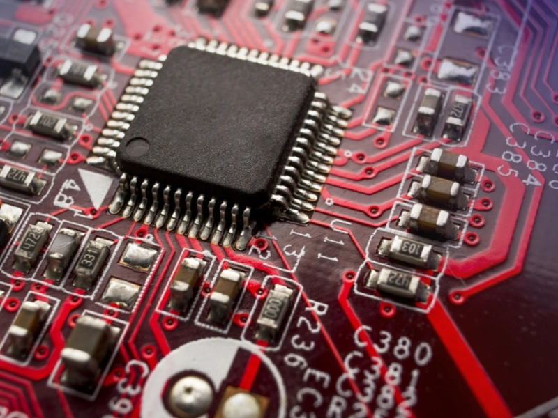
PCBA stands for Printed Circuit Board Assembly. While the terms PCB (Printed Circuit Board) and PCBA are sometimes used interchangeably, they refer to distinct stages of electronic manufacturing. A bare PCB is the green fiberglass board with copper traces but no components. PCBA adds the electronic components—resistors, capacitors, integrated circuits, and connectors—that bring the board to life.
The assembly process converts a passive substrate into an active electronic system capable of processing signals, controlling functions, and communicating with other devices. This transformation requires precise placement of components, reliable solder connections, and thorough testing to verify proper function.
Early electronics relied on through-hole technology (THT), where component leads passed through holes in the circuit board and were soldered on the opposite side. This approach provided strong mechanical bonds but limited miniaturization and required more board space.
Surface Mount Technology (SMT) revolutionized electronics manufacturing by placing components directly onto the board surface without through-holes. SMT enables higher component density, smaller board sizes, faster assembly speeds, and reduced manufacturing costs. Today, approximately 90% of electronic assemblies use surface mount technology, with through-hole components reserved for applications requiring superior mechanical strength.
The assembly process begins with applying solder paste to the bare PCB. A stencil—typically laser-cut stainless steel—aligns precisely over the board, and squeegees spread solder paste across its openings. The paste, a mixture of fine solder particles suspended in flux, adheres only to the exposed pad areas where components will eventually connect.
Solder paste selection depends on the specific alloy requirements, component thermal profiles, and final product applications. Lead-free solders (typically tin-silver-copper alloys) have become mandatory for consumer electronics under RoHS regulations, while some aerospace and medical applications still specify traditional tin-lead solders for their superior wetting properties and reliability.
Modern assembly lines use automated pick-and-place machines to position components with remarkable speed and accuracy. These systems use vision systems to identify component orientation, vacuum nozzles to pick up parts from reels or trays, and precision linear motors to place components onto the board with tolerances measured in microns.
Placement speed varies widely depending on component size and accuracy requirements. High-speed machines can place 50,000 components per hour on consumer electronics boards, while precision placement systems for complex medical or aerospace assemblies prioritize accuracy over throughput, typically achieving placement rates of 5,000 to 15,000 components per hour.
After component placement, the board enters the reflow oven—a precisely controlled conveyor furnace that melts the solder paste, creating permanent electrical and mechanical connections. The reflow profile typically includes four stages: preheat to activate flux and evaporate solvents, thermal soak to equalize component temperatures, peak heating to melt solder, and controlled cooling to solidify joints without thermal shock.
Profile optimization proves critical for product quality. Too high a peak temperature damages sensitive components, while insufficient heat creates cold solder joints that fail prematurely. Quality manufacturers use thermocouples and data loggers to verify profiles for each unique board assembly, maintaining records that demonstrate process control during quality audits.
Post-reflow inspection identifies defects before boards proceed to final assembly. Automated Optical Inspection (AOI) uses cameras and image analysis software to detect component placement errors, tombstoning (where components stand upright), insufficient solder, and bridging between adjacent pads. For boards with hidden solder joints beneath components, X-ray inspection reveals internal connections that optical systems cannot see.
Functional testing validates board performance beyond simple connectivity. In-circuit testing (ICT) probes individual circuits to verify component values and solder joint integrity. Functional test fixtures apply power and signals to the board, executing test routines that simulate real-world operation. Flying probe testers offer flexibility for low-volume assemblies without custom fixture costs.
Many modern assemblies require software programming after physical assembly. Microcontrollers, FPGAs, and programmable memory devices need firmware loaded before the board becomes functional. Manufacturers use dedicated programming equipment—JTAG programmers, ICSP interfaces, or in-system programming stations—to load software while minimizing handling damage risks.
Configuration data such as calibration constants, serial numbers, and encryption keys often load during this stage. Secure programming procedures protect sensitive data from unauthorized access, while traceability systems record programming details for warranty and compliance purposes.
The Institute for Printed Circuits (IPC) establishes industry standards that define acceptable quality levels for electronic assemblies. IPC-A-610 governs product acceptability criteria, specifying visual standards for solder joints, component placement, and documentation requirements. IPC-A-600 addresses bare board acceptability, while J-STD-001 defines soldering process requirements and training qualifications.
Manufacturers pursuing IPC certification train their personnel to standardized skill levels and subject their processes to periodic audits. While certification isn't legally required for all applications, it provides objective evidence of manufacturing competence that procurement teams increasingly demand.
Different applications impose unique quality requirements beyond general standards. Automotive electronics must withstand extreme temperatures, vibration, and humidity while maintaining decades of reliable operation. IATF 16949 certification establishes quality management requirements specific to automotive supply chains, including production part approval processes (PPAP) that document manufacturing capability for each part number.
Medical device PCBA falls under FDA regulations and ISO 13485 quality management requirements. These assemblies demand rigorous documentation, traceability from component lot numbers to finished goods, and validation of manufacturing processes that affect product safety and effectiveness.
When evaluating potential manufacturing partners, technical capabilities determine what's possible. Minimum feature sizes, layer count limits, and component size restrictions vary significantly between facilities. A manufacturer specializing in consumer electronics may struggle with the fine-pitch components and dense routing that advanced military systems require.
Review the manufacturer's equipment inventory, including placement machine capabilities, inspection systems, and testing equipment. Ask about their experience with similar products—prior exposure to comparable assembly complexity reduces learning curve risks and improves first-pass yield on new projects.
Sophisticated quality systems separate reliable manufacturers from those that simply promise good results. Look for facilities that maintain complete process documentation, implement statistical process control, and conduct regular internal audits. Third-party quality certifications (ISO 9001, AS9100, ISO 13485) provide independent verification of quality system effectiveness.
Defect tracking and analysis capabilities indicate how manufacturers respond when problems occur. Mature quality organizations categorize defects by type, track trends over time, and implement corrective actions that prevent recurrence. Ask potential partners about their scrap rates, first-pass yield statistics, and customer return rates to quantify quality performance.
Component availability increasingly challenges electronics manufacturing. Long lead times, counterfeit components, and supply disruptions affect production schedules across the industry. Strong manufacturing partners maintain strategic component inventories, qualify multiple sources for critical parts, and implement counterfeit prevention programs that verify component authenticity.
Component obsolescence planning helps manage lifecycle risks for products with long production runs. Manufacturers who proactively communicate about end-of-life components and suggest alternatives prevent sudden production stoppages that cost both time and money.
PCBA costs divide into two categories: non-recurring engineering (NRE) costs that occur once per product, and unit production costs that repeat for each board manufactured. NRE expenses include tooling (stencils, fixtures, and program development), test development, and documentation preparation. Higher volumes spread NRE across more units, reducing per-board costs.
Prototype and low-volume production typically commands premium pricing because setup costs dominate. Understanding this cost structure helps product teams balance development budgets against production economics, potentially staging product launches to align with volume breakpoints.
Component costs often represent 60-80% of total board cost, making component selection critical for cost management. Standard components with multiple sources generally cost less and supply more reliably than proprietary or specialized parts. Design-for-manufacturing (DFM) reviews help optimize component choices, pad geometries, and routing to maximize production efficiency.
Panel utilization—the percentage of the production panel occupied by your boards—significantly affects manufacturing economics. Designs that pack efficiently onto standard panel sizes achieve lower per-board costs than those requiring custom panel dimensions or leaving substantial unused area.
Consumer electronics drive relentless miniaturization, pushing manufacturers to place smaller components with tighter tolerances. Chip-scale packages (CSP), wafer-level packaging (WLP), and embedded component technologies enable continued size reduction even as traditional SMT approaches reach physical limits.
Wearable electronics, medical implants, and compact consumer devices increasingly use flexible circuit assemblies that bend and fold to fit unconventional form factors. Rigid-flex PCBA combines rigid boards with flexible substrates, enabling three-dimensional packaging that rigid-only designs cannot achieve.
Manufacturing sustainability impacts both regulatory compliance and brand reputation. Lead-free assembly has become standard, but the industry continues exploring halogen-free materials, water-soluble fluxes, and energy-efficient processes that reduce environmental footprint while maintaining product quality.
A PCB (Printed Circuit Board) refers to the bare board—the substrate with copper traces but no electronic components attached. PCBA (Printed Circuit Board Assembly) includes all the components soldered onto the board, creating a functional electronic assembly ready for installation in end products.
Lead time varies based on complexity, volume, and manufacturer capacity. Prototype quantities typically ship within 1-2 weeks, while high-volume production runs may require 4-8 weeks depending on component availability and scheduling. Rush services often available at premium pricing for time-critical requirements.
First-pass yield measures the percentage of boards that pass all inspections and tests without rework or repair. High first-pass yield indicates efficient manufacturing processes and quality design. World-class manufacturers achieve first-pass yields exceeding 98% on complex assemblies, reducing total production cost and delivery time.
X-ray inspection penetrates component bodies and board substrates to reveal hidden solder joints beneath BGAs (Ball Grid Arrays), QFNs (Quad Flat No-leads), and other area-array packages. These packages hide their solder connections from optical inspection, making X-ray essential for verifying connection integrity in modern dense assemblies.
ISO 9001 represents the baseline quality management standard. IATF 16949 applies to automotive electronics, ISO 13485 addresses medical devices, and AS9100 covers aerospace applications. IPC certification demonstrates soldering process competency and personnel qualifications.
Many contract manufacturers offer flexible capacity that accommodates prototype quantities (1-25 pieces), pilot runs (100-500 pieces), and high-volume production (thousands of units monthly). However, capabilities vary significantly—verify that potential partners have proven experience across your anticipated volume range.
PCBA represents the essential manufacturing technology that transforms electronic designs into functional products. Understanding the assembly process, quality requirements, and partner selection criteria empowers decision-makers to navigate the complex landscape of electronics manufacturing with confidence.
Whether developing a prototype for proof-of-concept or scaling production for global distribution, selecting the right PCBA manufacturing partner significantly impacts product quality, time-to-market, and total cost of ownership. Invest time in evaluating capabilities, quality systems, and communication practices during supplier selection—these foundational decisions echo throughout the product lifecycle.
How to Evaluate a Reliable Prototype PCB Assembly PartnerJuly/29/2026
What's the Difference Between Prototype PCB Assembly and Low Volume PCB Assembly ?May/18/2026
Understanding AOI (Automated Optical Inspection) in PCB Assembly Quality ControlJuly/28/2026

What Are the Benefits of Small Batch PCB Assembly?May/18/2026
What is Low Volume PCB Assembly?May/18/2026