Open Nav


Every electronics engineer has experienced the frustration of opening reflowed boards and finding defects that shouldn't be there—tombstoned components, solder bridges, insufficient joints, or voids in solder connections. The root cause typically isn't mysterious manufacturing errors—it's thermal profile optimization. A properly tuned reflow soldering profile eliminates most thermal defects by ensuring all components reach their ideal temperature at the right time without exceeding safe limits.
Understanding reflow profiles isn't just about following guidelines from paste manufacturers. It's about the physics of heat transfer, material behavior, and how different components respond to thermal cycles. This guide explains what makes effective profiles, how to optimize them for your specific assemblies, and which thermal defects to watch for and prevent.
Reflow soldering transforms paste from a mixture of solder alloy particles and flux into solid solder joints through controlled heating. This transformation happens through multiple physical and chemical processes, each requiring specific temperature ranges and timing. Get one aspect wrong, and defects appear—sometimes immediately, sometimes later as reliability issues.
Components themselves introduce thermal complications. Different materials expand at different rates during heating, creating mechanical stress. Heavy components heat slower than small ones. Leads may reach liquidus temperature before bodies, creating thermal differentials across the same component. An optimized profile accounts for these variations while ensuring reliable solder joints across all component types.
The stakes extend beyond immediate defects. Thermal shock during reflow can damage components or create latent defects that cause failures in the field. Insufficient reflow creates weak joints that fail under vibration or thermal cycling. Overheating can degrade component characteristics or materials. A well-designed profile prevents these issues while maximizing yield and reliability.
Many manufacturers accept rework rates of 1-2% as normal, attributing them to "typical" production challenges. In reality, most of these defects result from thermal profiles that don't match the assembly's actual requirements. A 1% rework rate on a 1000-board batch means 10 boards need manual rework—each requiring skilled technicians time, additional materials, and potential risk to other components.
The financial impact includes direct costs (rework labor, replacement components, additional testing) and indirect costs (delayed deliveries, reduced productivity, potential customer impact). Hidden costs include technician fatigue from repetitive rework tasks and the risk of introducing new defects during rework operations. Profile optimization that reduces rework from 2% to 0.2% can save significant money while improving product quality.
Effective reflow profiles follow predictable patterns across multiple thermal zones. While specific temperatures and times vary based on solder paste specifications and assembly characteristics, the fundamental structure remains consistent. Understanding these zones helps diagnose problems and optimize profiles systematically rather than through trial and error.
The preheat zone begins the thermal journey, gradually raising board temperature from ambient to roughly 100-150°C over 60-90 seconds. This gradual rise serves multiple critical functions: volatile solvents in the flux evaporate slowly without causing splattering, components warm uniformly reducing thermal shock risks later, and the paste mixture begins activating in preparation for the melt phase.
Preheat rate—the speed of temperature increase—matters significantly. Too fast, and flux volatiles escape rapidly creating splattering and potential solder ball formation. Too slow, and board throughput suffers while flux may degrade before the active phase. Most solder paste manufacturers recommend preheat rates between 1-3°C per second as a starting point, though exact optimization depends on board size, component density, and conveyor speed.
The preheat zone also begins activating flux chemistry. Modern fluxes contain activators that begin removing oxides from component leads and PCB pads at temperatures below liquidus. This activation requires time—if preheat is too short or insufficiently controlled, flux hasn't properly prepared surfaces for wetting, potentially causing insufficient solder joints.
Between preheat and active reflow, many profiles include a soak zone where temperature stabilizes or rises very gradually for 60-120 seconds. During soak, several critical processes occur simultaneously across the assembly. Flux activation continues, oxide removal progresses, and the entire assembly reaches more uniform temperature reducing thermal gradients before entering the reflow zone.
The soak zone is particularly important for boards with mixed component types—large heavy components heat slower than small surface mount devices, and the soak allows thermal equilibrium. Components like BGAs with significant thermal mass benefit from soak zones ensuring the entire component reaches appropriate temperature before solder melts. Without adequate soak, component centers may remain significantly cooler than surfaces during reflow, creating joint defects.
Not all profiles require explicit soak zones. Lead-free assemblies with fine-pitch components often use optimized profiles without distinct soak phases, relying on controlled ramp rates through the pre-reflow region instead. However, for most leaded assemblies and complex mixed-technology boards, soak zones improve consistency and reduce defects.
The reflow zone comprises the most critical thermal phase—temperature rises above solder liquidus, typically exceeding 220°C for leaded solder or 235-250°C for lead-free alloys. During this phase, solder particles melt, wet surfaces, and form solder joints. Peak temperature and time above liquidus (TAL) determine joint quality and component integrity.
Peak temperature must exceed liquidus by sufficient margin to ensure complete melting and wetting across all joints. However, excessive peak temperature creates problems: component degradation, PCB delamination, flux residue charring, and reduced joint strength. For leaded solder, peaks typically range 225-245°C; for lead-free, 245-260°C represents common ranges, though exact values depend on specific solder alloy specifications.
Time above liquidus—how long the assembly stays above solder melt temperature—equally matters. Too short, and solder hasn't properly wet surfaces or fully form joints. Too long, and intermetallic compounds grow excessively degrading mechanical properties. TAL typically ranges 30-90 seconds, with shorter times for lead-free alloys which are more sensitive to intermetallic growth.
After reflow, controlled cooling solidifies solder joints into their final configuration. Cooling rate affects solder microstructure, joint strength, and stress distribution. Rapid quenching creates fine-grained structures with different mechanical properties than slow cooling. Proper cooling rate depends on solder alloy and assembly requirements—typically 2-4°C per second for leaded solder, slightly slower for lead-free.
Too rapid cooling creates thermal shock and potential component cracking, particularly for temperature-sensitive devices. Too slow cooling increases production throughput and may create undesirable grain structures in solder joints. The cooling zone also completes flux activity—remaining flux residues solidify during cooling, ideally leaving clean, conductive surfaces without needing extensive cleaning.
Cooling continues until board temperature drops below approximately 100°C, after which boards can be safely handled without risk of joint deformation or component damage. The exact endpoint depends on assembly materials and handling requirements, but most manufacturers use 80-100°C as the practical exit temperature.
Understanding the relationship between profile parameters and specific defects helps optimize profiles systematically rather than reacting to problems after they occur. Many defects trace directly to profile characteristics that can be adjusted once the underlying cause is identified.
Tombstoning occurs when small components like 0402 or 0201 resistors and capacitors stand up on one end during reflow, creating open circuits. The root cause is uneven wetting between the two terminations—one side's solder melts and wets before the other, pulling the component upward through surface tension as the other side remains wetted to the pad.
Profile factors contributing to tombstoning include uneven heating across components, rapid ramp rates causing differential wetting, and insufficient soak time allowing thermal equilibrium between terminations. Tombstoning typically results from preheat or soak issues rather than reflow zone problems, though excessive peak temperatures can exacerbate the phenomenon.
Solutions include reducing ramp rates through preheat, extending soak times, ensuring even heating across the assembly, and optimizing pad design. For particularly challenging assemblies, nitrogen environments reduce oxidation and improve wetting consistency, reducing tombstoning incidence.
Bridging creates unintended solder connections between adjacent leads or pads, creating shorts. This common defect typically results from excessive solder volume, insufficient paste deposition control, or thermal profiles causing solder to flow excessively during reflow. Profile-related causes include rapid temperature rise creating splattering, excessive peak temperature causing excessive fluidity, and insufficient cooling before boards exit the oven.
Bridge prevention requires attention to paste deposition accuracy and profile optimization. Reduce ramp rates through preheat to minimize splattering, optimize peak temperature to the minimum required for proper wetting, and ensure adequate cooling to solidify joints before board movement. For fine-pitch components, profiles with slightly lower peaks and longer TAL often reduce bridging compared to aggressive profiles.
Nitrogen reflow environments help reduce bridging by preventing oxidation that increases solder surface tension and promotes spreading. While nitrogen doesn't solve all bridging problems, it provides additional margin for fine-pitch assemblies.
Insufficient solder wetting creates weak joints that may fail under mechanical stress or thermal cycling. Symptoms include dull grainy solder surfaces, poor fillet formation, and exposed component leads or pad surfaces after reflow. Profile causes include insufficient peak temperature, inadequate TAL, and poor preheat reducing flux activation.
Optimizing for insufficient wetting involves ensuring peak temperature exceeds liquidus by adequate margin, extending TAL to allow complete wetting, and improving preheat to maximize flux activation. Components with heavy thermal mass like BGAs often require slightly higher peak temperatures or longer TAL to ensure internal joints properly wet.
Insufficient wetting sometimes results from process issues beyond profiles—inadequate paste volume, poor stencil design, or aged paste. However, profile optimization can compensate for marginal process conditions by ensuring maximum flux activity and proper thermal conditions.
Voids—gas pockets trapped within solder joints—reduce current-carrying capacity and potentially weaken mechanical connections. They form when flux volatiles or moisture trapped in paste or components vaporize during reflow but cannot escape before solder solidifies. Profile optimization significantly affects void formation.
Rapid preheat causes flux volatiles to escape violently, creating splattering and potential voiding. Adequate preheat with controlled ramp rates allows gradual volatile escape before solder melts. For components particularly prone to voiding like BGAs, extended soak times before reflow help volatiles escape from component undersides and underfill areas.
Cooling rate also affects voiding—too rapid cooling can trap gases that would otherwise escape through still-molten solder. Controlled cooling with rates matching paste manufacturer recommendations reduces void formation. For void-sensitive applications, vacuum reflow systems can actively extract gases during reflow, dramatically reducing void levels.
Excessive thermal stress during reflow can damage components in ways that may not be immediately obvious. Examples include capacitor cracking from thermal shock, IC package delamination, plastic deformation of connectors, and degradation of temperature-sensitive materials like certain plastics or coatings. Profile optimization prevents these failures by respecting component thermal limits.
Component datasheets specify maximum storage and soldering temperatures—typically 260°C for most commercial components, though military or automotive grades may have lower limits. Profiles must respect these maximums while still achieving proper reflow conditions. Thermal shock occurs during rapid temperature transitions—particularly cooling rates exceeding component specifications.
For temperature-sensitive assemblies, profiles may use lower peak temperatures with extended TAL, or multiple reflow passes for complex assemblies. Slow ramp rates through critical temperature ranges reduce stress. Component placement planning—grouping temperature-sensitive components together—allows profile sections optimized for their requirements without compromising other components.
Effective profile optimization combines theoretical understanding with practical experimentation. While solder paste manufacturers provide recommended profiles as starting points, optimal profiles require adjustment based on specific assembly characteristics. Systematic approaches to profile development yield better results than random experimentation.
Solder paste manufacturers provide recommended profiles based on their specific formulations. These profiles serve as excellent starting points because they're developed through extensive testing of the paste's characteristics. However, these recommendations assume ideal conditions—specific board sizes, component densities, and oven configurations that rarely match actual production exactly.
When starting profile development, begin with the manufacturer's recommended profile and adjust based on your assembly's specific requirements. Record all profile parameters in a systematic way—zone temperatures, conveyor speed, board entrance and exit temperatures. This documentation allows repeatability and provides baseline data for optimization.
Accurate profile measurement requires proper tools. K-type thermocouples attached to critical points on the assembly measure actual temperatures rather than oven zone settings. Attach thermocouples using high-temperature solder or adhesive, positioning them at representative locations: large thermal mass components, fine-pitch areas, board edges, and center regions.
Thermal profiler devices provide continuous temperature recording throughout the oven, generating actual profile curves. These systems connect to multiple thermocouples and record data at high frequency, capturing temperature variations across the assembly. Modern profilers provide analysis features showing ramp rates, TAL, peak temperatures, and other critical parameters automatically.
Profile measurement should occur on production-qualified assemblies with full component loading. Empty boards or partially populated assemblies heat differently than complete boards, giving misleading profile data. For consistency, use the same board type for profile optimization that will actually run in production.
Profile optimization works best when approached systematically rather than making random adjustments. Begin by measuring the actual profile with your starting settings. Identify which parameters differ from targets and prioritize adjustments based on which deficiencies cause the most significant problems.
Adjust one parameter at a time, measure results, and assess impact. For example, if preheat ramp rate is too high, adjust zone temperatures to reduce the rate, measure the new profile, and check whether the change addressed the problem without creating new issues. This systematic approach prevents chasing problems in circles.
Document each adjustment and its results. This documentation provides a history of what worked and what didn't, valuable for future profile development and troubleshooting. When problems arise during production, profile history helps identify whether recent changes might have contributed.
Profile optimization culminates in validation through production runs under actual conditions. Small pilot runs before full production identify issues that appear only at volume. Monitor defect rates during validation runs, categorizing defects by type to understand whether profile optimization addressed targeted problems or revealed new issues.
Validation should include electrical testing, visual inspection, and X-ray inspection where appropriate. X-ray reveals internal joint characteristics invisible to visual inspection, particularly for BGAs and other leadless components. Defect categorization helps confirm whether profile optimization solved targeted problems without introducing new issues.
After successful validation, document the final profile parameters and create standard operating procedures for running this profile in production. Standardization ensures consistency across shifts and operators, preventing profile drift that gradually introduces defects over time.
Once basic profile optimization is mastered, advanced techniques provide additional capabilities for challenging assemblies. These approaches address specific manufacturing challenges and can further reduce defects while maintaining or improving throughput.
Nitrogen reflow environments reduce oxygen levels in the oven, decreasing oxidation during heating. Reduced oxidation improves solder wetting, reduces defects like insufficient joints and tombstoning, and can allow lower peak temperatures while achieving proper wetting. Nitrogen also reduces flux residue formation, potentially eliminating cleaning requirements for some applications.
Nitrogen reflow requires oven modifications and ongoing nitrogen supply, adding operational costs. However, for fine-pitch assemblies, lead-free applications, or boards with significant mixed component technologies, the benefits often justify the investment. Nitrogen levels typically maintained between 20-1000 ppm oxygen, with lower levels providing greater benefit at higher cost.
Nitrogen reflow doesn't eliminate the need for proper profile optimization—profiles still must deliver appropriate thermal cycles. However, nitrogen provides additional margin, reducing defect sensitivity to minor profile variations.
Vacuum reflow systems actively remove gases from solder joints during reflow, dramatically reducing void levels. These systems apply vacuum during the reflow zone, extracting vaporized flux volatiles and other gases from molten solder before solidification. Void reduction rates exceeding 90% are achievable compared to conventional reflow.
Vacuum reflow particularly benefits BGAs, which are prone to voiding in bottom-side joints. For applications where voiding affects reliability or electrical performance—power electronics, RF applications, high-current connections—vacuum reflow provides significant advantages. Systems require specialized equipment and process adjustments but deliver measurable quality improvements.
Complex assemblies with mixed component technologies sometimes benefit from multi-stage profiles using different thermal sections for different components. For example, a profile might include a lower-temperature reflow pass for temperature-sensitive components followed by a higher-temperature pass for components requiring higher peak temperatures. Alternatively, selective reflow tools apply heat only to specific assembly sections.
Multi-stage approaches add complexity and cost but enable assembly combinations impossible with single-pass profiles. For applications mixing through-hole and surface mount components, combining wave soldering with reflow in controlled sequences provides optimal results. Similar approaches work for mixing leaded and lead-free components when full transition isn't feasible.
Advanced reflow systems include real-time monitoring and adaptive control capabilities that adjust profiles based on actual thermal data rather than fixed parameters. Thermocouples monitoring board exit temperatures feed data to control systems that adjust zone temperatures dynamically to maintain target profile parameters despite load variations.
Adaptive control reduces sensitivity to loading variations, production mix changes, and other factors that cause profile drift. While requiring significant investment in equipment and process development, adaptive control delivers consistent quality across varying production conditions without constant operator intervention.
Profile optimization isn't a one-time activity—it requires ongoing management as products, materials, and production conditions change. Establishing good practices for profile management ensures continued quality and prevents gradual quality degradation.
Profiles can drift over time due to oven calibration changes, conveyor variations, or other factors. Regular verification using thermal profilers ensures profiles remain within specification. Most manufacturers verify profiles weekly or monthly depending on production volume and criticality.
Verification should measure profiles on representative assemblies, not just test boards. Production load affects heating characteristics, so verification should reflect actual production conditions. Record profile data systematically to track trends and identify drift before it causes quality issues.
Maintain comprehensive documentation for all profiles including zone temperatures, conveyor speeds, target profile parameters, and acceptance criteria. Implement change control procedures for profile modifications to prevent unauthorized changes that could introduce defects.
Documentation should include information about which assemblies use which profiles, effectively linking profile data to production requirements. When new products introduce profile changes, update documentation systematically to maintain accurate records across the product portfolio.
Ensure operators and technicians understand profile fundamentals and their impact on quality. Training reduces errors, improves troubleshooting capabilities, and promotes consistent profile usage across shifts and operators. Knowledge sharing across production lines helps disseminate best practices and prevent isolated optimization efforts that might introduce problems elsewhere.
Create reference materials showing common defect types and their profile-related causes. These quick reference guides help operators quickly identify and address profile-related problems during production, reducing downtime and defect rates.
Profiles don't exist in isolation—they interact with other process variables like paste deposition, component placement accuracy, and cleaning processes. Effective profile management considers these interactions rather than treating profiles as independent parameters. For example, profile optimization might reveal paste deposition issues that need stencil design changes.
Regular process reviews examine profiles in context of overall process health. When quality problems emerge, systematic review of all process variables—profiles included—provides the best path to effective solutions.
Lead-free profiles require higher peak temperatures—typically 235-260°C compared to 220-245°C for leaded solder—due to higher liquidus temperatures of lead-free alloys. Lead-free alloys also require different cooling rates and are more sensitive to excessive time above liquidus, which can cause excessive intermetallic growth. Additionally, lead-free profiles often use nitrogen environments more frequently to improve wetting since lead-free alloys generally have poorer wetting characteristics than leaded solder.
Verification frequency depends on production volume, application criticality, and equipment stability. For high-volume production or safety-critical applications, weekly or daily verification may be appropriate. For lower-volume production, monthly verification typically suffices. Always verify profiles after equipment maintenance, significant production changes, or when defect patterns suggest profile variations. Establish a verification schedule appropriate to your specific situation and follow it consistently.
In theory, a single profile might work for multiple boards if they have similar thermal characteristics. However, in practice, different boards typically require at least minor profile adjustments for optimal results. Boards with different component densities, thermal masses, or component types will experience different thermal characteristics under the same profile. While using a common profile simplifies operations, custom profiles for different board types typically deliver better quality. If using a single profile for multiple boards, choose a compromise setting that works adequately for all types, recognizing that none may be optimal for any specific board.
Several factors cause profile drift: oven calibration changes, conveyor speed variations, thermocouple degradation, load variations, and environmental changes like ambient temperature fluctuations. Regular maintenance addresses many of these factors—calibration verification, conveyor maintenance, and thermocouple replacement. Load variations from different production mixes require profile adjustments or adaptive control systems. Monitoring profile trends helps identify drift before it causes quality issues.
Several signs indicate profile-related defects: defects consistently occurring on specific board types or component types, defects varying with oven position or load, sudden changes in defect patterns following profile changes, or defects that correlate with profile measurements outside specification. X-ray inspection of solder joints provides additional diagnostic information—joint characteristics like wetting angles, void levels, and intermetallic formation reveal profile quality. Correlating defect data with profile measurements helps identify causal relationships.
Reflow soldering profiles represent one of the most critical variables determining PCB assembly quality. Properly optimized profiles eliminate most thermal defects, improve yield, and enhance product reliability. Poor profiles create rework, waste, and potentially reliability issues that impact customer satisfaction.
Understanding profile fundamentals—thermal zones, temperature relationships, defect causes—enables systematic optimization rather than random adjustment. With proper measurement tools, systematic approaches, and ongoing management, profiles become reliable quality enablers rather than sources of frustration and variation.
The investment in profile optimization pays dividends through reduced rework, higher yields, and better product quality. For electronics manufacturers competing on quality and reliability, excellent reflow profiles aren't optional—they're essential operational capabilities that differentiate manufacturers and products in the marketplace.
The Science of Solder Paste Printing: Keys to Perfect SMT AssemblyMay/19/2026
The Shift Towards Miniaturization in Electronics AssemblyJune/26/2026
Precision SMT PCB Assembly for Wearable TechnologyJune/16/2026
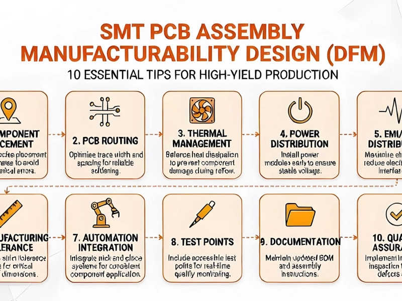
Top 10 DFM (Design for Manufacturability) Tips for SMT PCB AssemblyJune/08/2026

The Rise of AI in SMT Quality InspectionJune/18/2026