Open Nav



In the fast-paced world of electronics manufacturing, the margin for error is virtually non-existent. A single misplaced component or a microscopic soldering defect can render a high-cost device useless. This is why implementing rigorous Quality Assurance Across the Entire Turnkey PCB Assembly Process is not just a regulatory requirement, but a critical business survival strategy. Whether you are producing medical devices, automotive controllers, or consumer IoT gadgets, the integrity of your Printed Circuit Board Assembly (PCBA) determines the product's longevity and safety.
Having spent over a decade on the SMT floor, I have seen firsthand how "quality control" is often mistaken for "quality assurance." While QC is about finding defects at the end, QA is about preventing them from happening in the first place. In this article, we will dive deep into the technical nuances of maintaining quality from the moment a Bill of Materials (BOM) is received to the final shipping of the unit.
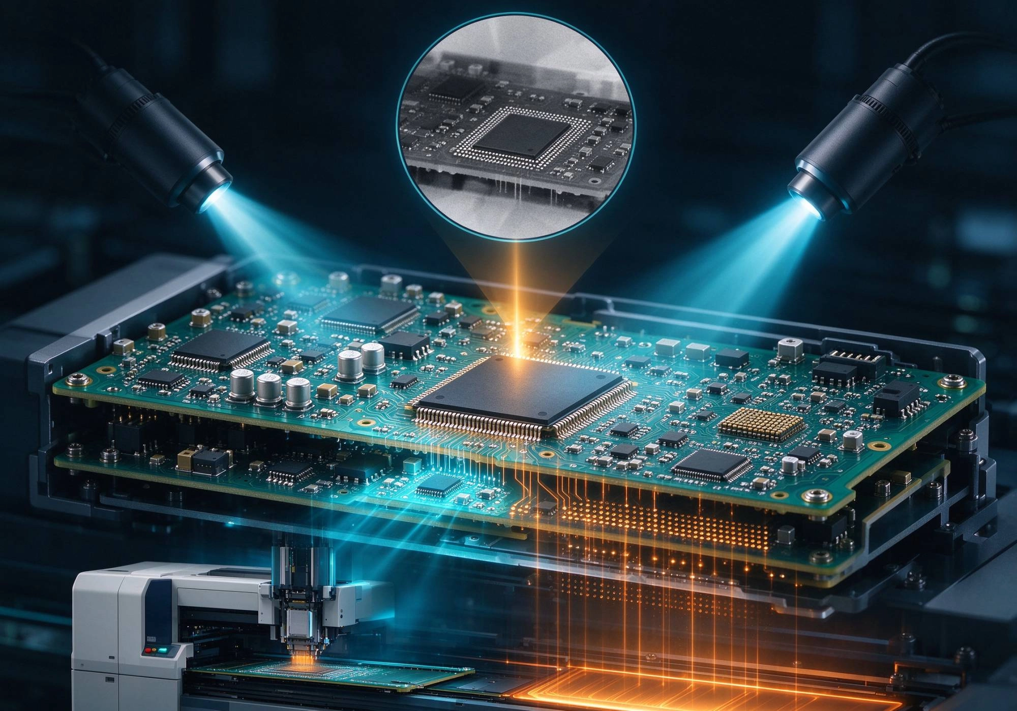
Many manufacturers make the mistake of thinking QA starts when the solder paste is printed. In reality, the most critical QA steps happen before the machines even warm up. This phase is often referred to as New Product Introduction (NPI).
Design for Manufacturability (DFM) and Design for Testability (DFT) are the first lines of defense. A robust QA process involves a detailed review of the Gerber files and the BOM. We look for common pitfalls such as:
In a turnkey model, the assembler sources the components. Therefore, the supply chain becomes a variable in the quality equation. Incoming Quality Control (IQC) must be strict. This involves verifying that components match the datasheets and checking for counterfeit parts. For sensitive components, we check the Moisture Sensitivity Level (MSL) ratings. If a component has exceeded its floor life, it must be baked according to IPC/JEDEC J-STD-033 standards before it can be placed on the board. Ignoring this step is a common error that leads to "popcorning" defects during reflow.
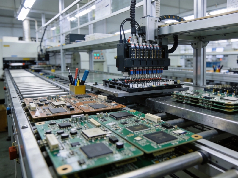
Once production begins, the focus shifts to process monitoring. This is where the concept of Quality Assurance Across the Entire Turnkey PCB Assembly Process becomes tangible on the factory floor. We rely heavily on automation to catch defects in real-time.
Statistics show that approximately 60-70% of soldering defects originate from poor solder paste printing. To mitigate this, we utilize 3D Solder Paste Inspection (SPI) machines immediately after the stencil printer. The SPI measures the volume, height, and area of the paste deposit. If the volume is too low, we risk an open circuit; too high, and we risk bridging. By catching these deviations early, we prevent defects from moving to the pick-and-place machine.
After components are placed and the board exits the reflow oven, Automated Optical Inspection (AOI) is performed. Modern AOI systems use high-resolution cameras and sophisticated algorithms to check for:
While AOI is powerful, it is not infallible. It can sometimes generate false calls, which is why skilled operators must verify the machine's findings. This human-in-the-loop approach ensures that we don't waste time reworking good boards.
With the miniaturization of electronics, Ball Grid Arrays (BGAs) and Quad Flat No-leads (QFNs) have become ubiquitous. Since the solder joints for these components are hidden underneath the package, optical inspection is useless. We employ X-Ray inspection to visualize the solder balls. This allows us to check for voids (air pockets in the solder), head-in-pillow defects, and shorting between balls. A voiding percentage of over 25% is generally considered a failure in high-reliability applications.
Visual inspection is only part of the battle. The board must also function electrically. This stage validates the Quality Assurance Across the Entire Turnkey PCB Assembly Process by ensuring the circuit performs as designed.
ICT is the gold standard for high-volume production. It uses a "bed of nails" fixture to contact test points on the PCB. It can detect shorts, opens, and measure component values (resistance, capacitance, inductance) to ensure they are within tolerance. While ICT requires an upfront investment in fixture design, it provides the most granular data regarding board health.
While ICT checks individual components, Functional Circuit Testing (FCT) simulates the final operating environment of the device. We power up the board and run firmware to verify that it communicates correctly, drives outputs, and reads sensors. FCT is the ultimate validation that the assembly process was successful.
True quality assurance is cyclical. We utilize data from SPI, AOI, and ICT to drive continuous improvement. If we notice a trend of tombstoning on a specific capacitor, we analyze the reflow profile or the stencil aperture design to correct the root cause. Documentation, such as First Article Inspection (FAI) reports, provides a traceable record that every step was executed correctly.
Sometimes, the operator forget to check the stencil tension before print, this is a small mistake but can cause big issue later. We must always double check the tension to ensure consistent paste release. Attention to these small details is what separates a good manufacturer from a great one.
Achieving high reliability in electronics manufacturing requires a holistic approach. By integrating rigorous DFM checks, real-time process monitoring via SPI and AOI, and comprehensive electrical testing, we ensure that every board leaving the factory meets the highest standards. Quality Assurance Across the Entire Turnkey PCB Assembly Process is not just a checklist; it is a culture of precision and accountability.
QA (Quality Assurance) is process-oriented and focuses on preventing defects through planning and system improvements. QC (Quality Control) is product-oriented and focuses on identifying defects in the finished product through inspection and testing.
X-Ray inspection is essential for inspecting components with hidden solder joints, such as BGAs, CGAs, and QFNs. It allows manufacturers to detect voids, shorts, and insufficient solder that cannot be seen with standard optical cameras.
Moisture Sensitivity Level (MSL) defines how long a component can be exposed to ambient air before it absorbs too much moisture. If a component exceeds its floor life, it must be baked to remove moisture; otherwise, the moisture can turn to steam during reflow, causing the component to crack or delaminate.
Medical PCBA: Meeting Strict Regulatory Standards in AssemblySeptember/01/2026
The Science of Solder Paste Printing: Keys to Perfect SMT AssemblyMay/19/2026
Customer Success Story: Solving Complex Thermal Issues in PCBASeptember/18/2026

Supply Chain Resilience: How Turnkey Providers Handle ShortagesSeptember/28/2026
The Growing Demand for Low Volume, High-Mix Assembly ServicesSeptember/30/2026