Open Nav



LED lighting has fundamentally transformed how we illuminate commercial spaces, industrial facilities, and residential environments. The efficiency gains are well documented: LEDs consume up to 75 percent less energy than incandescent alternatives while delivering significantly longer operational lifetimes. Yet behind these performance advantages lies a manufacturing discipline that demands precise engineering and specialized processes. Metal core printed circuit boards represent the backbone of reliable LED assembly, enabling the thermal management that high-power lighting applications require.
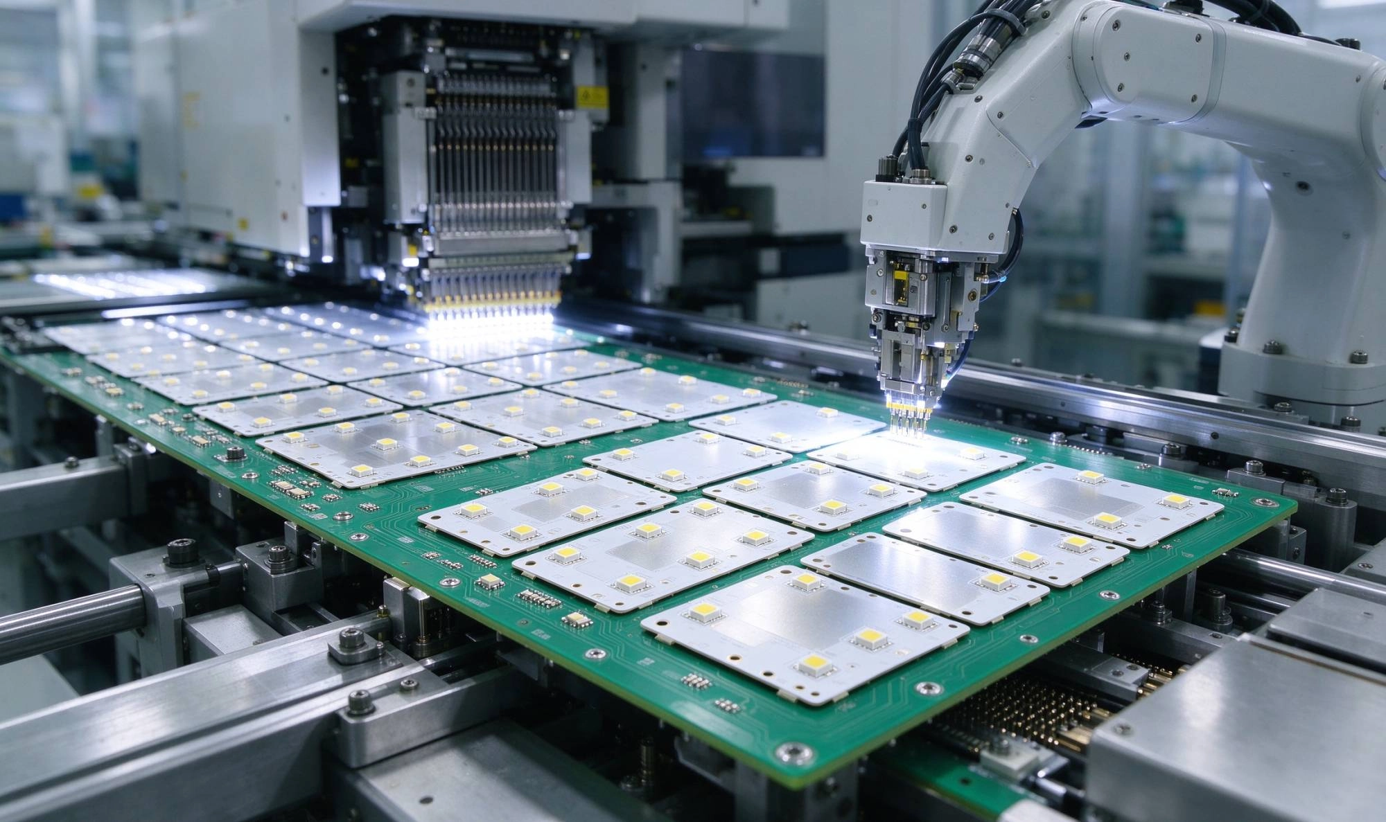
Heat is the silent enemy of LED longevity. Unlike traditional incandescent bulbs that radiate heat outward, LEDs generate thermal energy at the semiconductor junction level. If this heat cannot escape efficiently, the LED junction temperature rises, causing lumen depreciation, color shifting, and accelerated component degradation. A junction temperature increase of 10 degrees Celsius can cut LED lifespan by half. This is not hyperbole — it is physics that every LED design must address.
Traditional FR4 circuit boards, constructed from fiberglass and epoxy resin, have thermal conductivity ratings of approximately 0.3 W/mK. For low-power indicator LEDs, this limitation presents few challenges. For high-bay warehouse fixtures, street lighting arrays, or automotive headlamp assemblies operating at tens of watts, FR4 simply cannot move heat fast enough to maintain safe operating temperatures. Metal core PCBs solve this problem directly by incorporating aluminum or copper substrates with thermal conductivity ratings reaching 200 W/mK or higher.
A metal core PCB consists of a metal base plate — typically aluminum, though copper offers superior thermal performance for the most demanding applications — covered by a dielectric layer and a copper circuit layer. The dielectric layer is engineered to provide electrical isolation while maximizing thermal transfer between the active circuitry and the metal base. Different dielectric materials offer tradeoffs between thermal resistance, electrical isolation strength, and cost.
The most common configurations include aluminum substrates with thermally conductive dielectric layers, IMS (insulated metal substrate) constructions that optimize the balance between thermal performance and manufacturing cost, and multilayer assemblies that incorporate thermal vias to channel heat away from sensitive components. Understanding these construction options enables engineers to select the appropriate substrate for their specific thermal and electrical requirements.
Aluminum represents the most widely used metal core material due to its favorable combination of thermal conductivity, weight, cost, and machinability. Aluminum substrates handle heat dissipation effectively for the majority of LED lighting applications while remaining economically practical for medium-volume production. The metal can be stamped, drilled, and finished using standard metalworking processes, keeping manufacturing costs manageable.
Aluminum core PCBs excel in applications ranging from residential recessed lighting to industrial high-bay fixtures. Their thermal resistance values typically fall in the range of 1.0 to 2.0 C-in²/W, enabling effective heat spreading across the metal base and into mounting surfaces or heat sinks. For designs requiring junction-to-case thermal resistance below 1.0 C/W, aluminum core assemblies routinely achieve these targets when properly engineered.
Copper offers approximately twice the thermal conductivity of aluminum, making it the material of choice for ultra-high-power LED assemblies where every fraction of a degree matters. Copper core PCBs appear frequently in automotive LED headlamp applications, high-performance industrial spotlights, and aerospace lighting systems where reliability requirements are exceptionally demanding. The tradeoffs include higher material costs, more complex machining requirements, and increased weight — considerations that rule out copper for many standard applications.
Thermal vias provide pathways for heat to travel from the top-side LED components through the dielectric layer to the metal base where it can dissipate into the surrounding environment. The geometry and density of thermal vias significantly impacts overall thermal resistance. Larger vias conduct more heat but reduce available copper routing area. Higher via density improves thermal performance but may compromise mechanical integrity or increase manufacturing complexity.
In practice, thermal via arrays with diameters of 0.3 to 0.5 millimeters, spaced at 1.0 to 1.5 millimeter pitch, provide effective thermal performance for most LED lighting applications. The vias should extend from directly beneath the LED package thermal pad through the dielectric layer to the metal core, filled with thermally conductive epoxy or plated to ensure minimal thermal resistance at the interface. This direct thermal connection between the LED junction and the metal base is what makes metal core PCBs so effective compared to standard FR4 designs.
LED lighting circuits typically carry relatively high currents at low voltages, particularly in designs operating from 12V or 24V supply rails. This current profile demands careful attention to trace width calculations and current density limits. A 3-amp LED driver output feeding multiple parallel LED strings requires wider copper traces than a logic-level signal line, even if the physical board dimensions are identical.
For metal core assemblies, the copper thickness options typically include 1 ounce, 2 ounce, and occasionally 3 ounce copper. Heavier copper reduces resistive heating and improves current handling capacity, but it also affects etching tolerances and can complicate the assembly process. Selecting 2 ounce copper for a high-power LED array provides a practical balance between current handling and manufacturing compatibility.
The thermal path does not end at the metal core PCB. Heat must flow from the PCB base into the fixture housing, a heat sink, or the surrounding air through natural or forced convection. Every interface in this thermal chain introduces resistance. Thermal interface materials (TIMs) — including thermal pads, phase-change compounds, and thermal greases — fill microscopic air gaps between surfaces, dramatically improving heat transfer efficiency.
When specifying mounting hardware, ensure that mechanical clamping forces distribute evenly across the PCB to avoid localized stress concentrations that could crack solder joints or damage components. Spring-loaded fasteners and distributed clamping patterns provide more reliable thermal connections than point-loaded bolt arrangements, particularly for large-format LED assemblies.
Metal core PCB assembly shares many processes with standard PCB assembly, including solder paste printing, component placement, and reflow soldering. However, the thermal properties of metal substrates introduce unique challenges that demand specialized expertise. The high thermal mass of aluminum and copper bases affects reflow profile development, while the different coefficients of thermal expansion between the metal core and copper circuitry create mechanical stresses that standard FR4 assemblies do not experience.
Lead-free solder alloys, mandated by RoHS regulations for most commercial LED products, require reflow temperatures exceeding 217 degrees Celsius. For metal core assemblies, the reflow oven must account for the substrate's ability to absorb and redistribute heat throughout the thermal profile. A typical lead-free profile might include a preheat zone ramping from 150 to 180 degrees over 90 seconds, a thermal soak zone maintaining 180 to 200 degrees for 60 to 120 seconds, and a peak temperature zone reaching 245 to 260 degrees for 30 to 60 seconds.
The extended thermal mass of metal core boards often requires adjustments to standard reflow profiles, including longer soak times to ensure uniform temperature across the entire assembly before reflow. Failure to account for these thermal characteristics can result in tombstoning, incomplete reflow, or delamination of the dielectric layer — defects that compromise both electrical reliability and thermal performance.
Modern high-power LEDs utilize surface mount packages with thermal pads on the bottom surface that must connect directly to the PCB copper for heat transfer. These packages, including mid-power LEDs, high-power COB (chip-on-board) LEDs, and chip-scale packages, require precise placement to ensure adequate solder paste coverage beneath the thermal pad. Misalignment of even a few tenths of a millimeter can create voids that increase thermal resistance and cause localized overheating.
AOI (automated optical inspection) following component placement verifies correct orientation and position for polarity-sensitive LEDs before reflow. X-ray inspection may be appropriate for BGA packages or other bottom-terminated components, though most LED packages use bottom thermal pad designs that are visually inspectable. After reflow, thermal imaging or thermistor measurements can confirm that the LED junction temperatures remain within specified limits under full load operation.
Reliable LED assemblies require comprehensive testing throughout the manufacturing process and at final inspection. In-circuit testing verifies that all passive components are correctly placed and soldered. Functional testing under simulated operating conditions confirms that the LED array performs to photometric specifications — lumen output, color temperature, and color rendering index. Burn-in testing at elevated ambient temperatures accelerates the identification of infant mortality failures before products ship to customers.
Thermal validation deserves particular attention for metal core LED assemblies. Thermocouple measurement of LED junction temperature during operation confirms that thermal design margins are adequate. If junction temperature approaches the LED manufacturer's maximum rating, design modifications — additional thermal vias, larger metal base, forced-air cooling, or reduced drive current — may be necessary before production release.
Street and area lighting fixtures operate continuously for 12 or more hours per day, year after year. The cumulative thermal stress on LEDs in these applications demands the most robust thermal management available. Metal core PCBs, coupled with properly designed heat sinks and consideration of natural convection patterns, deliver the reliability that municipal lighting specifications require.
Industrial high-bay fixtures for warehouses and manufacturing facilities must illuminate large volumes while enduring harsh environments including temperature extremes, humidity, and vibration. Metal core LED assemblies handle these conditions reliably when properly encapsulated and protected against moisture ingress. The initial investment in robust thermal management pays dividends through extended fixture lifetime and reduced maintenance requirements in facilities where lift truck scheduling and working-at-height risks make luminaire access expensive.
Automotive interior and exterior lighting presents unique challenges including extreme temperature ranges, vibration, and strict reliability requirements. Metal core LED assemblies meet these demands through rigorous design margins and manufacturing processes validated to automotive quality standards. The trend toward LED-based headlamps and adaptive lighting systems has accelerated the adoption of copper core PCBs in premium automotive applications where thermal and optical performance justify the added cost.
What is the main advantage of metal core PCBs for LED applications?
Metal core PCBs provide dramatically superior thermal conductivity compared to standard FR4 boards. This enables high-power LEDs to operate within their rated junction temperature limits, extending operational lifetime and maintaining photometric performance over time.
Can metal core PCBs be used for multilayer LED assemblies?
Yes, multilayer metal core PCBs are available, though they involve more complex construction with multiple dielectric and copper layers separated by prepreg materials. These constructions are typically used for LED drivers and control electronics rather than the primary LED mounting substrate.
What is the typical lifespan of a metal core LED assembly?When properly designed with adequate thermal margins, LED assemblies on metal core PCBs commonly exceed 50,000 hours of operation with less than 10 percent lumen depreciation. This lifespan far exceeds traditional lighting technologies and provides compelling total-cost-of-ownership advantages.
Are metal core LED assemblies more expensive than FR4 alternatives?
Metal core PCBs carry higher material and manufacturing costs than standard FR4 boards. However, for applications exceeding approximately 5 watts of LED power, the superior thermal performance and reliability of metal core assemblies provide better overall value when lifecycle costs are considered.
What quality standards apply to LED metal core assemblies?
IPC standards including IPC-A-610 for assembly quality and IPC-6012 for PCB qualification provide frameworks for ensuring consistent quality. Automotive applications typically require compliance with IATF 16949 quality management requirements. Industrial and commercial LED products may need UL listing or equivalent safety certifications.
Contact us to discuss your requirements.
Medical PCBA: Meeting Strict Regulatory Standards in AssemblySeptember/01/2026
Panelization Strategies: Saving Money on Your PCB Assembly OrderOctober/27/2026
Quality Assurance Across the Entire Turnkey PCB Assembly ProcessOctober/15/2026
Scaling Up: Transitioning from Prototype to Low Volume ManufacturingOctober/28/2026
Avoiding Tombstoning and Bridging in Your PCB LayoutJuly/30/2026