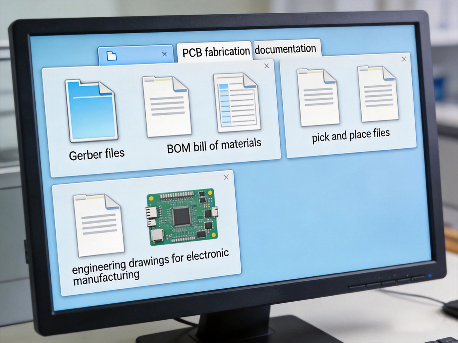
You've designed your PCB, sourced your components, and you're ready to move from prototype to production. But there's one critical step before your board arrives at the manufacturer: assembling the complete package of design files and documentation that your contract manufacturer (CM) needs to assemble your boards correctly.
The question "what files do I need to submit?" seems straightforward, yet incomplete or incorrect documentation causes delays, miscommunications, and assembly errors. Different manufacturers have slightly different requirements, but there's a core set of files that every CM needs. Understanding these requirements—and why they matter—ensures smooth manufacturing and accurate results.

Essential Manufacturing Files
Gerber Files
The foundation of PCB manufacturing, Gerber files describe every layer of your board:
- Top and bottom copper layers: Circuit patterns for routing
- Top and bottom solder mask layers: Protective coating with openings for pads
- Top and bottom silkscreen layers: Component designators and markings
- Drill file: Hole locations, sizes, and types
- Drill charts: Legend for drill symbols and sizes
- Inner layer copper files: For multi-layer boards (usually GTS, GBS for ground, GTP, GBP for power)
- Board outline/dimension layer: Mechanical layer defining board shape and size
Format Requirements
Most manufacturers accept Gerber RS-274X format:
- Extended Gerber: RS-274X (preferred) - includes aperture definitions embedded
- Standard Gerber: RS-274D - requires separate aperture files (outdated, avoid if possible)
- Units: Typically inches or millimeters; specify clearly
- Resolution: 2:5 or 2:6 format (e.g., 2:5 means 2 digits before decimal, 5 after)
Common Mistakes
Avoid these Gerber file errors:
- Missing layers or incorrect layer assignments
- Mixed units (inches vs. millimeters) within the same file set
- Incomplete drill charts or undefined drill symbols
- Incorrect board outline dimensions
- Solder mask overlapping or covering pads inappropriately
Bill of Materials (BOM)
The BOM tells the CM what components to purchase and install:
- Component reference designator: C1, R1, U1, etc.
- Part number: Manufacturer part number or detailed description
- Component description: Resistor, capacitor, IC, connector, etc.
- Value: 10kΩ, 0.1μF, 5V regulator, etc.
- Package/footprint: 0805, SOIC-8, QFN-16, etc.
- Quantity: Number of components required
- Manufacturer: Component manufacturer name
- Optional specifications: Tolerance, voltage rating, temperature range, etc.
Format Requirements
BOM format flexibility exists but consistency is key:
- CSV format: Most common, universally readable
- Excel format: Widely accepted, but ensure compatibility
- Columns clearly labeled: Header row identifying each column's purpose
- No merged cells or complex formatting: Keep it simple for easy parsing
BOM Best Practices
Avoid BOM-related delays:
- Include alternate part numbers where suitable
- Specify tolerances and critical parameters
- Mark components as "DNP" (Do Not Populate) if intentionally uninstalled
- Group similar components together (all resistors, all capacitors, etc.)
- Verify component availability before submission
- Include package dimensions if using non-standard footprints
Pick-and-Place File (Centroid File)
This file tells assembly equipment where to place components:
- Reference designator: C1, R1, U1 (matches BOM)
- X coordinate: Component X position on board
- Y coordinate: Component Y position on board
- Rotation angle: Component orientation in degrees
- Component type/package: Resistor, capacitor, IC, etc.
- Side of board: Top or bottom layer
Format Requirements
Multiple formats are common:
- IPC-D-356A: Industry standard format
- CSV format: Simple text format, widely used
- Centroid file: General term for pick-and-place data
- Units: Typically millimeters or inches; specify clearly
Common Pick-and-Place Issues
Ensure accurate placement data:
- Coordinates must match actual component positions (check alignment with Gerber)
- Rotation angles must be correct (0°, 90°, 180°, 270° typically)
- Designators must match BOM exactly
- Include all components intended for assembly
- Specify board side (top vs. bottom) clearly
Assembly Drawings and Documentation
Assembly Drawings
Assembly drawings provide visual guidance:
- Component placement reference: Visual reference for component locations
- Assembly notes: Special assembly instructions or requirements
- Orientation indicators: Polarization marks for diodes, ICs, connectors
- Acceptance criteria: What constitutes acceptable assembly quality
- Reference designators: Map between board positions and BOM entries
Engineering Notes
Communicate special requirements clearly:
- Special assembly techniques: Hand soldering, selective soldering, rework procedures
- Component handling requirements: Moisture sensitivity, ESD precautions
- Testing requirements: Functional testing, AOI inspection criteria, ICT test points
- Conformal coating requirements: If coating is needed after assembly
- Reference documents: Standards or specifications that must be followed
Fabrication Drawings
For bare board manufacturing:
- Material specifications: Laminate type, copper weight, surface finish
- Board dimensions: Final board size with tolerances
- Hole specifications: Plating, sizes, tolerances
- Solder mask and silkscreen requirements: Colors, coverage
- Special features: Blind/buried vias, controlled impedance, etc.
Additional Files by Application Type
High-Frequency and RF Designs
Additional requirements for RF work:
- Impedance requirements: Target impedance values and tolerances
- Transmission line specifications: Microstrip, stripline parameters
- Dielectric requirements: Specific material for RF performance
- Shielding specifications: Cans, fences, or shielding requirements
High-Power and Thermal Designs
For power electronics:
- Thermal requirements: Heat sink specifications, thermal interface materials
- Copper weight specifications: Heavy copper requirements
- Thermal via specifications: Via arrays and fill requirements
- Current handling specifications: Trace current carrying requirements
High-Density and Fine-Pitch Designs
For complex assemblies:
- Stencil design requirements: If you're providing stencils
- Fine-pitch handling notes: Special handling for 0.4mm pitch and below
- Underfill requirements: If needed for BGA/QFN reliability
- Component placement orientation: Specific requirements for polarized components
Automotive and Safety-Critical Designs
For regulated industries:
- Traceability requirements: Material lot tracking, component traceability
- Compliance documentation: UL, CE, automotive grade requirements
- Reliability testing specifications: Burn-in, HAST, thermal cycling requirements
- PPAP requirements: Production Part Approval Process documentation if applicable
File Organization and Submission
File Structure Best Practices
Organize files for clarity:
- Use clear file naming: Project name + file type + version
- Create logical folder structure: Separate gerbers, BOMs, documentation
- Include README file: Brief overview of contents and special requirements
- Version control: Maintain version numbers and change logs
Submission Checklist
Before submitting, verify:
- All Gerber layers present and correctly labeled
- Drill file and drill chart included
- BOM complete with all required components
- Pick-and-place file coordinates verified
- Assembly drawings or notes included
- Fabrication specifications clear
- Any special requirements documented
- Contact information for questions
Delivery Methods
Submit files appropriately:
- Secure file transfer: Use manufacturer's portal or secure FTP
- Email for small packages: File size permitting (typically <25MB)
- Cloud sharing: For large file sets, use cloud storage services
- Physical media: DVDs or USB drives (less common, but acceptable)
Common Submission Mistakes
Missing or Incomplete Files
Most common issues:
- Missing inner layer Gerbers for multi-layer boards
- Missing drill chart or undefined drill symbols
- Incomplete BOM missing critical components or parameters
- Missing pick-and-place file or incorrect file format
- Missing assembly drawings or insufficient documentation
Incorrect File Formats
Format-related problems:
- Using RS-274D Gerber format instead of RS-274X
- Mixed units within file sets (inches vs. millimeters)
- BOM with merged cells or complex formatting
- Pick-and-place files with inconsistent coordinate systems
Ambiguous or Conflicting Information
Documentation clarity issues:
- Conflicting specifications between fabrication and assembly drawings
- Unclear material specifications
- Ambiguous tolerance requirements
- Missing special instructions that should have been documented
Outdated or Unverified Data
Version control problems:
- Submitting outdated Gerber files
- BOM and pick-and-place file mismatch
- Using old component specifications without checking availability
- Submitting prototype files for production quantities
Working with Your Contract Manufacturer
Pre-Submission Communication
Engage early for clarity:
- Request file submission guidelines: Get manufacturer-specific requirements
- Discuss special requirements: Complex features, tight tolerances, unique components
- Clarify expectations: What's included, what's additional cost
- Review timeline: Understand lead times for review and production
Review and Feedback
Expect review from your CM:
- DFM review: Design for manufacturability feedback on your design
- Question clarifications: CM will ask about ambiguous items
- Cost estimates: Changes that affect pricing
- Timeline adjustments: Additional time for complex assemblies
Change Management
Handle revisions systematically:
Track all changes: Document modifications and their reasonsUpdate all affected files: Don't update BOM without updating pick-and-placeClearly mark revisions: Version numbers, revision letters, datesCommunicate changes: Keep CM informed of all revisionsKey Takeaways
- Complete Gerber files (copper, mask, silkscreen, drill, outline) are the foundation of PCB manufacturing
- BOM with clear component specifications (part number, value, package) tells the CM what to purchase
- Pick-and-place file provides coordinates for automated assembly equipment
- Assembly drawings and documentation communicate special requirements and acceptance criteria
- Additional documentation may be required for high-frequency, high-power, fine-pitch, or regulated applications
- Organize files clearly, verify completeness, and include README or overview documentation
- Common mistakes include missing layers, incorrect formats, ambiguous specifications, and version mismatches
- Pre-submission communication with your CM prevents confusion and delays
- Expect DFM review and be prepared to respond to questions and feedback
- Maintain rigorous change control throughout design revisions
Frequently Asked Questions
Can I submit Eagle or Altium project files directly?
Most manufacturers prefer standard file formats (Gerber, BOM, pick-and-place) rather than native CAD files. While some manufacturers accept native files, they may charge extra for file conversion, and you lose control over the output quality. Always generate industry-standard files from your CAD tool and submit those instead. This ensures you know exactly what your manufacturer receives and can verify the output matches your intentions.
What format should my BOM be in?
CSV format is universally accepted and the safest choice. Excel format is also widely used, but avoid complex formatting, merged cells, or formulas that could cause parsing issues. The key is clarity and consistency: clearly labeled columns, no special characters that could cause parsing errors, and complete information for each component. Many manufacturers provide BOM templates—using their template ensures compatibility.
Do I need to submit separate fabrication and assembly files?
For full turnkey service (both bare board fabrication and assembly), submit all files together. For bare board fabrication only, submit Gerber files, fabrication drawings, and drill files. For assembly only (using boards you already have), submit BOM, pick-and-place files, assembly drawings, and specifications for the boards you're providing. Clarify with your CM which service you're requesting and confirm what files they expect for that scope.
What if I don't have pick-and-place coordinates?
Most CAD tools can generate pick-and-place files automatically—check your tool's documentation or export options. If you absolutely cannot generate the file, some manufacturers offer conversion services at additional cost. However, manual entry of pick-and-place data increases cost and potential for errors. If this is a limitation, discuss it with your CM during the quoting process to understand the cost and timeline impact.
How detailed should my assembly drawings be?
Assembly drawings should be detailed enough that a technician could assemble the board correctly with no additional context. Include component locations, orientation indicators (polarization marks), special assembly notes, and acceptance criteria. For simple boards, minimal documentation may suffice. For complex or critical assemblies, more detailed drawings reduce the risk of miscommunication and assembly errors. When in doubt, more documentation is better than less.
Submitting complete, accurate documentation is the foundation of successful PCB manufacturing. By understanding what files are required and why they matter, you can ensure your boards are manufactured correctly, on time, and within budget. Remember: the time spent preparing thorough documentation is far less than the time and cost of correcting problems caused by incomplete or incorrect submissions.