Open Nav



Last spring, a medical device manufacturer approached us with a problem that had been quietly undermining their product for nearly six months. Their portable diagnostic device was passing all the standard electrical tests at the factory, was being packaged, shipped, and installed at hospitals across the country. But within three to six months of field deployment, a small but consistent percentage of units were failing — not dramatically, not completely, but in the subtle way that medical devices can least afford: intermittent operation, fluctuating sensor readings, and eventually a complete system lockout that required on-site service. The manufacturer had tracked the failure rate to approximately 2.5 percent of the production volume, which sounds small until you realize that for a device used in emergency diagnostics, a 2.5 percent failure rate is a patient safety issue and a brand reputation crisis. They had spent weeks examining their firmware, their power management circuits, and their enclosure thermal design. The problem, as they eventually discovered, was hiding inside the HDI PCB — specifically in the microvia barrels that connected the layers of the board together.
The failure manifestation in the field was consistent enough to pattern, even though it was intermittent at the individual unit level. The diagnostic device would operate normally during the initial power-on sequence, would pass its self-test, and would begin the measurement cycle. After 15 to 45 minutes of operation, when the internal temperature of the device had risen from room temperature to its normal operating temperature of approximately 55 degrees Celsius, the system would develop communication errors between the main processor board and the sensor interface board. The communication error was being detected by the firmware, which logged the error and eventually triggered a system reset. On the bench, the units would often pass all tests, including the thermal stress test that the manufacturer had been using as their quality gate. Only the longer-duration thermal cycling, with the extended dwell times at temperature extremes, would eventually expose the failing units.
The manufacturer had initially suspected the connectors, then the firmware timing, then the power supply ripple. They had replaced the connector supplier, tightened the firmware timing margins, and added additional filtering to the power rails. The failure rate did not change. It was only when they performed a detailed failure analysis on the returned units, including cross-sectioning of the PCB at the communication interface, that the truth emerged: the microvia barrels connecting the inner signal layer to the surface pads were cracking under thermal cycling stress. The crack was not complete — it was intermittent, making electrical contact at lower temperatures and losing contact as the board expanded with heat. The thermal expansion mismatch between the copper plating in the microvia barrel and the dielectric material surrounding it was causing barrel fatigue, exactly the kind of failure that is difficult to detect in standard electrical testing and that only manifests after cumulative thermal cycling.
When we were brought in to help investigate, the first thing we did was to review the microvia structure in the HDI board. The board was a 6-layer sequential build-up HDI design with two HDI layers on each side of a standard 2-layer core. The microvia diameter was 150 microns, laser-drilled through the HDI dielectric to connect the surface pads to the inner signal layer. The barrel plating was specified as 20 microns minimum copper, which is within the normal range for microvia plating. On the surface, everything looked correct. But when we examined the cross-sections from the failed units, the problem became clear: the plating in the barrel was not uniform. There were voids at the barrel-to-pad interface, and in some cases, the copper plating showed a columnar grain structure that is the hallmark of poor electroplating control. The voids and the poor plating structure were stress concentration points that accelerated the fatigue cracking under thermal cycling.
We obtained the plating process records from the board fabricator and found the smoking gun. The plating bath for the HDI layers was being operated at a current density that was at the upper end of the acceptable range, and the bath chemistry was not being analyzed and adjusted at the recommended frequency. The result was a plating process that was producing barrel copper with inconsistent grain structure, with voids at the interface between the plating layers, and with a tendency toward nodule formation that created stress concentrations in the barrel. The process was capable of producing good vias when conditions were optimal, but it was not robust to the normal variation that occurs in any manufacturing process. The manufacturer had been receiving boards from this fabricator for over a year without incident, but the process drift had finally crossed the threshold where the microvia reliability was compromised.
We also examined the thermal cycling conditions that the boards were experiencing in the field. The medical device was being used in hospital environments where the ambient temperature could range from 18 to 30 degrees Celsius, and the device self-heated to 55 degrees Celsius during operation. The thermal cycle from power-on to thermal equilibrium and back to power-off was occurring 5 to 8 times per day in typical use, which meant approximately 2,000 to 3,000 thermal cycles per year. The board was specified to survive 1,000 thermal cycles from minus 20 to plus 85 degrees Celsius based on the IPC-6012 Class 3 qualification standard. But the qualification testing had been performed on the first article boards from the original production run, before the plating process drift had degraded the via quality. The boards that were now failing in the field had been fabricated 8 to 12 months later, when the plating process had shifted further from its optimal condition.
The fix required action at multiple levels, because the problem had multiple root causes. The first action was the immediate containment of the field failures, which meant identifying the affected production lots and initiating a recall and replacement program for the units that were at the highest risk of failure. The manufacturer used the production records, which fortunately included the board fabrication date and the lot number, to identify the boards that were manufactured during the period when the plating process was most out of control. Approximately 35 percent of the field units fell within this window and were replaced proactively before they could fail.
The second action was the investigation and correction of the plating process at the board fabricator. We worked with the fabricator's process engineering team to analyze the plating bath conditions, the current density settings, the agitation parameters, and the bath maintenance schedule. The root cause analysis identified three contributing factors: the current density was set 15 percent above the recommended level, the organic content of the bath was not being measured frequently enough to detect the accumulation of organic breakdown products, and the plating rack loading was inconsistent, with some panels receiving higher current density than others due to the non-uniform rack geometry. The fabricator implemented a corrective action plan that included the reduction of the current density to the center of the recommended range, the implementation of a weekly organic content analysis with automatic bath renewal when the organic level exceeded the threshold, and the redesign of the plating rack to achieve more uniform current distribution.
The third action was the requalification of the HDI board for the medical device application. We designed a thermal cycling test program that was more representative of the actual field use conditions, including the real temperature range, the real dwell times, and the real number of cycles that the boards would experience over the product lifetime. The requalification testing was performed on boards from the corrected fabrication process, and all test boards survived the required number of cycles without microvia failure. The requalification results were documented in a supplemental qualification report that was submitted to the regulatory authority as part of the device's quality system documentation.
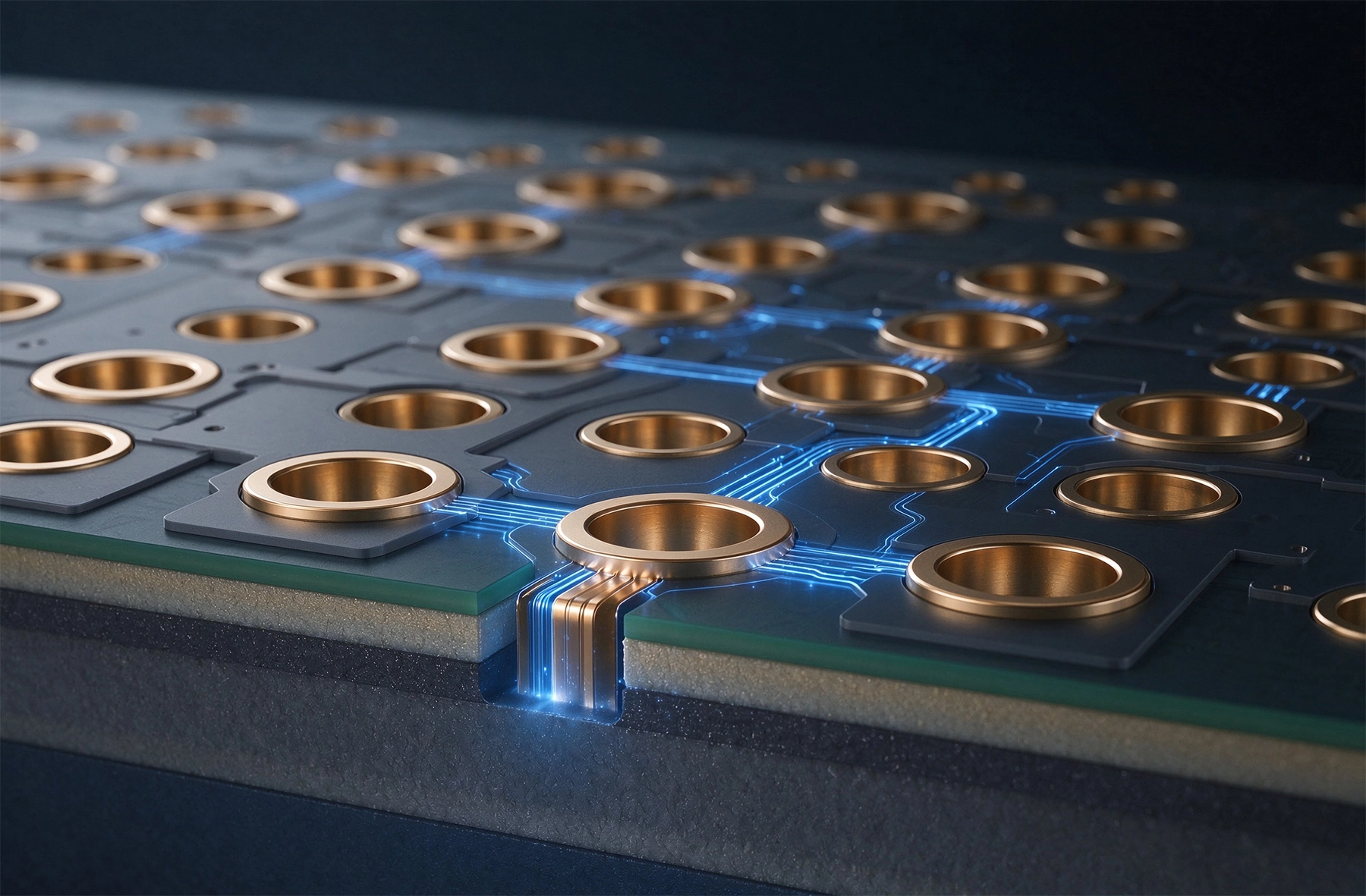
The most important lesson from this case is that microvia reliability is not guaranteed by a specification alone. The specification of 20 microns minimum barrel plating is necessary but not sufficient to ensure reliable microvia performance under thermal cycling. The quality of the plating, not just the thickness, determines the fatigue resistance of the microvia. The grain structure, the presence of voids, the interface adhesion between the plating layers, and the absence of nodules and cracks are all factors that affect the fatigue life and that are not captured in a simple thickness measurement. The incoming inspection of HDI boards must include the verification of the plating quality, not just the plating thickness.
The second lesson is that the qualification testing must be representative of the actual field conditions. The IPC thermal cycling specification is a useful baseline, but it may not reflect the specific thermal environment of a given application. A medical device that operates at elevated temperature and experiences frequent power cycles may impose a more severe thermal cycling demand on the PCB than a specification that was written for a general-purpose industrial environment. The thermal cycling test for HDI boards should be designed based on the actual field thermal profile, not just the minimum required by the standard. The number of cycles, the temperature range, and the dwell time should all be tailored to the application.
The third lesson is that the supplier relationship matters as much as the supplier specification. The manufacturer who has a close relationship with their PCB fabricator, who receives regular process capability reports, and who engages with the fabricator on process improvement issues is less likely to be surprised by process drift than the manufacturer who treats the fabricator as a commodity vendor. The fabricator in this case had the capability to produce reliable microvias — they had demonstrated it in the original qualification. But without the customer engagement that would have flagged the process drift early, the drift went undetected until the field failures appeared. The regular review of the process control charts and the plating bath maintenance records by the manufacturer's quality team would have caught the drift before it caused field failures.
If you are designing or sourcing HDI PCBs for applications where the microvia reliability is critical, there are specific actions you can take to reduce the risk of the kind of failure we described in this case. The first action is to specify the microvia plating quality, not just the thickness. The specification should include the grain structure requirement, the maximum void content, the maximum nodule size, and the interface adhesion requirements. These requirements can be verified through cross-section analysis of production samples, and the acceptance criteria should be defined in terms that are measurable and enforceable.
The second action is to implement incoming inspection of the microvia quality. The cross-section analysis of representative samples from each production lot is the most reliable method for verifying the microvia plating quality. The cross-section sampling plan should be defined based on the lot size and the criticality of the application, with a minimum of one cross-section per production lot for standard applications and multiple cross-sections for high-reliability applications. The cross-section results should be documented and compared against the qualification baseline to identify any degradation in the plating quality over time.
The third action is to design the thermal cycling test based on the actual field conditions. The test temperature range, the dwell time, the ramp rate, and the number of cycles should all be based on the expected field thermal profile, not just the minimum required by the standard. The test should be performed on production boards from each significant production lot, and the test results should be trended over time to detect any degradation in the thermal cycling reliability. The failure analysis of any boards that fail the thermal cycling test should include cross-sectioning of the failed vias to determine the failure mode and the root cause.
The microvia reliability challenge in HDI boards is real and is more common than the industry acknowledges, because the failures are intermittent, are difficult to detect with standard electrical testing, and often do not manifest until the board has been in service for months or years. The case we described in this article is not an isolated incident but is representative of the kind of reliability problem that occurs when the microvia plating quality is not adequately controlled and when the thermal cycling qualification is not based on the actual field conditions. The good news is that the problem is solvable. The microvia reliability can be achieved through the specification of plating quality requirements, the verification of plating quality through incoming inspection, and the design of thermal cycling tests that are representative of the actual field conditions.
The investment in a robust microvia reliability program is justified for any application where the HDI board will be subjected to thermal cycling and where the board failure would have significant consequences. The cost of the incoming inspection, the thermal cycling test, and the supplier engagement is small relative to the cost of a field failure, a product recall, and the damage to the brand reputation that follows a reliability failure in a safety-critical application. For product teams that are committed to HDI board reliability, the lessons from this case provide a practical roadmap for the quality practices that make the difference between a board that lasts and a board that fails.
Contact us to discuss your HDI board reliability requirements and to explore how our manufacturing capabilities and quality assurance practices can support the reliable performance of your HDI products.
Manual vs. Automated PCB Assembly: When to Use Which?October/09/2026
How Does Turnkey PCB Assembly Work? From BOM to Box BuildJune/29/2026

How Do You Ensure Component Authenticity in Turnkey Assembly?October/19/2026

The Economics of Outsourcing: Why Turnkey Services Save Money?November/10/2026

Understanding AOI (Automated Optical Inspection) in PCB Assembly Quality ControlJuly/28/2026