Open Nav



Most modern PCB assembly lines are optimized from end to end for surface mount technology. Pick and place machines whir at impressive speeds, placing thousands of components per hour. Reflow ovens maintain precise temperature profiles that melt solder and create reliable joints across hundreds of boards per shift. AOI systems inspect every joint for defects in seconds. The entire operation is tuned for efficiency, and anything that breaks the rhythm of this optimized flow immediately becomes a bottleneck. Then a board arrives with a through-hole barrel connector, a tall electrolytic capacitor that cannot be placed by machine, a press-fit header that requires special tooling, or a handful of odd-form components that simply cannot run through the standard SMT process. Suddenly, the highly optimized line is forced into manual workarounds that cost time, introduce variability, and create quality risk. Understanding how to handle odd-form components in an SMT-dominant line is not optional; it is a necessary skill for any assembly operation that wants to serve diverse customer needs without grinding to a halt every time a non-standard part appears on the BOM.
This article covers the complete landscape of odd-form component handling in SMT-dominant assembly operations, from the types of components that create challenges to the specific processes and equipment used to integrate them into an otherwise surface mount workflow. Whether you are managing an assembly line, engineering a product for manufacturability, or simply trying to understand how mixed-technology boards get built, the principles described here will help you navigate the real-world complexity that exists alongside the idealized SMT assembly process.
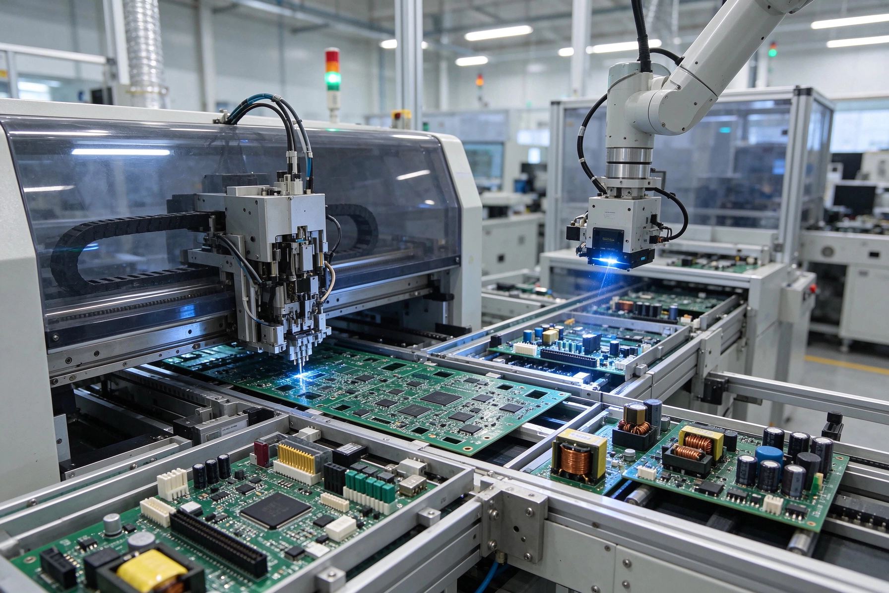
The term odd-form component covers a broad range of parts that do not fit the standard SMT paradigm of a flat package placed by an automated machine onto a flat PCB surface. The common thread is that these components cannot be processed through the standard SMT line without special handling, additional equipment, or manual intervention.
Through-hole components are the most common category of odd-form parts. Axial-lead components like resistors and capacitors with wire leads extending from both ends require the leads to be inserted into holes in the PCB before soldering. Radial-lead components like electrolytic capacitors have both leads on one side and may be inserted from the top or bottom depending on the design. These parts cannot be placed by standard SMT machines because they require physical insertion into holes, not placement onto pads on the surface.
Large or tall components that exceed the clearance envelope of standard pick and place machines are another category. A large electrolytic capacitor standing 20mm tall may be too tall for the nozzle clearance of some machines, or too heavy for standard placement forces. Connectors with tall bodies or complex housings may physically interfere with the machine's placement head or with adjacent components already on the board. Transformers, inductors, and other magnetic components with ferrous cores may interfere with magnetic-based part presentation systems used by some placement machines.
Components with non-standard terminations, like press-fit pins, card-edge contacts, or solder-cup connectors, require special processes that SMT equipment cannot perform. Press-fit components have compliant pins that are designed to be pressed into plated through-holes with a specific insertion force, creating a gas-tight connection without solder. Solder-cup connectors require solder to be applied inside each cup before the wire is inserted, a process that is fundamentally incompatible with standard SMT reflow.
Some components are classified as odd-form not because they cannot be placed by machine, but because they require processing steps that are incompatible with the standard SMT flow. Components that must be hand-soldered after reflow, or that require post-assembly programming, calibration, or adjustment, fall into this category. While these parts may be machine-placed, they create an off-line process requirement that interrupts the smooth flow of the SMT line.
Handling through-hole components in an SMT-dominant line ranges from fully manual insertion on one end of the spectrum to fully automated axial-lead insertion machines on the other. The choice of method depends on the volume, the complexity of the through-hole component mix, and the budget available for specialized equipment.
Manual through-hole insertion is the most flexible approach and the starting point for most assembly operations. An operator inserts component leads through the appropriate holes in the board, bends the leads slightly on the bottom side to hold the part in place, and the board proceeds to wave soldering or hand soldering to make the connections. Manual insertion works well for low volumes, complex mixed-technology boards with many different through-hole parts, and prototyping. The limitations are speed, consistency, and labor cost. An operator can insert perhaps 100 through-hole components per hour; at high volumes, the labor cost becomes prohibitive, and the variability between operators introduces quality inconsistency.
Semi-automatic insertion machines bridge the gap between manual and fully automatic. These machines automatically feed components from a reel or tube and present them to the operator for insertion, reducing fatigue and improving speed compared to pure manual insertion. Some machines also clinch the leads automatically after insertion, holding the component in place without requiring the operator to bend leads manually. A well-trained operator using a semi-automatic insertion machine can achieve 300 to 500 insertions per hour, a significant improvement over manual-only approaches.
Fully automatic axial-lead insertion machines are the high-volume solution for boards with large quantities of standard through-hole components like resistors and capacitors. These machines automatically cut leads to length, form the leads, insert them into holes, and clinch or cut the leads in a single high-speed operation. Insertion rates of 20,000 to 40,000 components per hour are achievable with modern equipment. The trade-off is setup time and cost; these machines require tooling specific to the component package sizes and board hole patterns, which means they are most economical for high-volume runs with consistent component mixes over many production batches.
After through-hole components are inserted, the joints must be soldered. For SMT-dominant lines, the choice is typically between wave soldering, which processes the entire bottom of the board in a single pass, and selective soldering, which solders individual joints or groups of joints with a focused solder fountain.
Wave soldering is the traditional approach for through-hole boards. The board passes over a standing wave of molten solder that contacts the bottom of the board and wicks up through the holes by capillary action, forming solder joints on both the component leads and the PTH barrel. Wave soldering is fast and cost-effective for boards with many through-hole parts on the bottom side, but it has significant drawbacks for mixed-technology boards. The entire bottom of the board is exposed to solder, which can damage or contaminate SMT components already placed on the top side. Solder bridges between adjacent SMT pads are a common defect, requiring careful process control and sometimes rework. The high thermal stress of wave soldering can damage heat-sensitive components if the board assembly includes them.
Selective soldering addresses many of the limitations of wave soldering by applying solder only where needed. A nozzle with a precisely shaped aperture positions the solder fountain over specific pins or groups of pins, soldering only those joints while leaving surrounding areas untouched. This focused approach protects nearby SMT components from thermal and solder exposure, reduces bridging defects, and allows boards with complex mixed-technology configurations to be processed without damage. The trade-off is speed; selective soldering is slower than wave soldering because each joint or group of joints must be processed sequentially. For boards with only a few through-hole components, selective soldering is often faster overall because it eliminates the setup and process time of wave soldering.
Some assembly operations use a combination approach: selective soldering for sensitive or complex through-hole areas, and wave soldering for boards with large numbers of through-hole parts where speed is more important than selectivity. This hybrid approach requires careful planning of the assembly sequence and may involve different processing routes for different board types within the same product family.
Press-fit technology offers an alternative to soldering for through-hole connections that provides gas-tight, highly reliable joints without the thermal stress of wave or selective soldering. Press-fit pins have a compliant section that deforms as it is inserted into a properly sized plated through-hole, creating spring pressure that maintains contact with the barrel wall and establishes a reliable electrical connection. No solder is required, which eliminates the risk of solder defects and allows processing of components that are thermally sensitive or otherwise incompatible with soldering.
Press-fit connectors are commonly used for high-reliability applications including automotive, industrial, and telecom where the connection must survive extreme temperatures, vibration, and thermal cycling without failing. The gas-tight connection created by press-fit technology is more resistant to thermal cycling fatigue than solder joints, which can crack over time under extreme thermal stress. Press-fit also allows field service and repair without the need for desoldering equipment; connectors can be removed and replaced by pressing them out and inserting new ones.
The process for press-fit insertion requires specific tooling to control the insertion force and ensure consistent results. Press-fit insertion tools apply a calibrated force to push the pin into the hole until a defined stop point is reached, ensuring that the compliant section engages properly with the barrel. Manual press-fit insertion is possible but inconsistent; automated press-fit insertion with force monitoring provides the most reliable results, particularly for high-volume production. The force required for insertion depends on the pin design and hole size, and must be high enough to ensure proper engagement but not so high as to damage the PCB or the connector housing.
PCB design rules for press-fit applications differ from standard through-hole design. The hole diameter must be precisely controlled to achieve the correct interference fit between the pin and the hole. Too tight a fit and the insertion force damages the barrel or the pin; too loose a fit and the spring pressure is insufficient to maintain reliable contact. Board thickness and hole plating quality also affect press-fit reliability. Close coordination between the designer, the PCB manufacturer, and the assembly operation is essential to ensure all three elements are compatible.
Hand soldering remains an essential tool in mixed-technology assembly, even in highly automated operations. Some components simply cannot be processed by machine or wave selective solder, and hand soldering is the practical solution. The challenge is integrating hand soldering into a line that is optimized for SMT throughput without creating a bottleneck or introducing unacceptable quality variability.
Hand soldering is typically performed after reflow for components that must be placed manually, or after wave or selective soldering for through-hole parts that require touch-up or repair. The key to managing hand soldering efficiently is to isolate it from the main flow of the line, routing boards that need hand work to a separate station where operators with specific training and equipment can complete the operations without disrupting SMT throughput.
Station setup for hand soldering should include temperature-controlled soldering irons appropriate for the component types being soldered, tips sized to the pad and hole dimensions, quality solder wire with appropriate flux core for the application, and fume extraction to protect operator health. For high-volume hand soldering of consistent component types, fixturing that holds the board and positions the component consistently reduces variability between operators and improves throughput.
Training and certification for hand soldering operators is critical for quality consistency. Hand soldering is highly dependent on operator skill, and inconsistent technique produces inconsistent joint quality. IPC standards provide training and certification requirements for hand soldering operators, including practical tests that verify the operator can produce joints meeting specified quality criteria. Investing in proper training pays back through reduced rework, fewer field failures, and more consistent first-pass yield.
Inspection of hand-soldered joints must be more thorough than inspection of machine-soldered joints because the variability is higher. Visual inspection using magnification should verify correct joint shape, adequate fillet formation, and absence of defects like cold joints, disturbed joints, or insufficient wetting. For critical joints, X-ray inspection or microsection analysis may be appropriate to verify internal joint quality that is not visible from the outside.
The sequence in which components are assembled onto a mixed-technology board has a significant impact on process efficiency and quality. A well-planned assembly sequence ensures that each process step is compatible with the components already on the board, avoiding damage from subsequent operations and minimizing the need for rework.
The general principle is to process the most temperature-sensitive and most fragile components last, after all soldering operations are complete. This means SMT placement and reflow happen first, followed by through-hole insertion and wave or selective soldering, followed by any hand-soldered components or post-solder operations like conformal coating or programming.
For boards with large through-hole components that would interfere with SMT placement or reflow, the sequence may need to be reversed for those specific parts. For example, a large transformer that sits tall on the board might prevent the placement head from reaching nearby SMT components, requiring the transformer to be hand-soldered after the SMT components are already in place. Similarly, through-hole components with plastic bodies that would melt in the reflow oven must be inserted and soldered after reflow.
The board orientation during wave soldering determines which side of the board is processed in the solder wave. If all through-hole components are on the top side, they cannot be wave soldered because the wave only contacts the bottom. These boards require selective soldering, hand soldering, or a wave soldering process that dips from the top side using a flood bar that applies solder from above. Understanding which process applies to which board configuration is essential for planning the assembly sequence correctly.
The best time to address odd-form component handling is during the design phase, before the board goes to manufacturing. Design for Manufacturability reviews that consider odd-form components and their integration with the SMT process can prevent costly production problems and reduce the cost of assembly.
Reducing the number of odd-form components in a design is the first DFM strategy. Where possible, use surface mount equivalents of through-hole parts. SMD electrolytic capacitors, SMD connectors with flat terminations, and SMD inductors are widely available and can be placed and soldered by the standard SMT line with no special handling. The cost and availability advantages of standard SMT parts almost always outweigh any performance advantage of the through-hole version for typical applications.
If through-hole parts are necessary, grouping them in accessible areas of the board simplifies insertion and reduces the complexity of the assembly sequence. Placing through-hole parts near the board edge, away from tall SMT components, allows easier access for insertion and soldering. Avoiding through-hole parts in dense BGA escape areas eliminates the risk of interference with fine-pitch SMT placement.
Specifying odd-form components with compatible termination styles reduces process complexity. Components with kinked or formed leads insert more easily and hold better in the hole before soldering than components with straight leads. Connectors with compliant press-fit pins should be specified with pins that match the PCB hole size and plating specifications of the manufacturer who will process them. Providing clear specifications for odd-form parts ensures that what is ordered matches what can be processed.
Odd-form components often present unique supply chain challenges that differ from standard SMT parts. Managing these challenges effectively prevents production delays and ensures that the assembly line is not idled waiting for a critical odd-form part.
Lead times for odd-form parts are often longer than for standard SMT parts, particularly for custom or specialty connectors that are not held in distributor stock. Building buffer inventory for critical odd-form parts protects against supply disruptions, but carrying excess inventory ties up working capital and risks obsolescence if the product design changes. The appropriate inventory strategy depends on the part criticality, the supplier lead time, and the predictability of demand.
Part presentation for odd-form insertion affects how efficiently the insertion process can run. Axial components supplied on radial tapes, in tubes, or in bulk all require different handling and feeding equipment. Selecting the presentation format that matches the insertion equipment available, or investing in equipment that handles multiple formats, simplifies the supply chain and reduces the risk of part-handling mismatches.
Alternate part qualification for odd-form parts takes more time than for standard SMT parts because the insertion and soldering processes are more sensitive to minor variations in lead style, body dimensions, and material compatibility. When an odd-form part goes obsolete or becomes unavailable, finding a substitute that works in the existing process without retooling or requalification can be challenging. Building relationships with multiple suppliers for critical odd-form parts, and qualifying alternates before they are needed, provides insurance against supply disruptions.
Quality control in mixed-technology assembly must address both the SMT-specific defects and the odd-form-specific defects that can occur. A comprehensive QC program covers all process steps and accounts for the interactions between them.
In-circuit testing provides comprehensive electrical verification of both SMT and through-hole connections by testing each net for opens, shorts, and correct component values. ICT requires test points or a bed-of-nails fixture that makes contact with accessible nodes on the board, which must be designed into the PCB from the beginning. For boards with many odd-form parts, the test coverage depends on the accessibility of test points for through-hole nets that may not be reachable from surface pads.
Functional testing verifies that the board performs its intended functions, catching defects that ICT cannot detect like firmware issues, timing problems, or subtle interaction failures between components. For mixed-technology boards, functional testing should include verification of through-hole connections that may not be fully exercised by ICT, like power distribution through large through-hole inductors or connectors where current flow may not be adequately tested by the ICT's limited test currents.
Visual inspection of odd-form solder joints is more challenging than inspection of SMT joints because the joint geometry is different and the inspection criteria differ. IPC-A-610 provides specific criteria for through-hole solder joints including fillet height, wetting angle, and void or crater visibility. Inspectors must be trained on these specific criteria for through-hole joints, which differ from the criteria for SMT terminations.
Several predictable challenges arise consistently in mixed-technology assembly. Recognizing these challenges and having plans to address them prevents them from becoming production-stopping problems.
Solder bridging between adjacent through-hole pins is one of the most common defects in mixed-technology assembly, particularly when wave soldering is used on boards with closely spaced through-hole pins. The solder wave can carry solder between adjacent pins, creating shorts that require rework. Selective soldering reduces this risk by limiting solder exposure to the specific pins being processed. For wave soldering, adjusting the board angle, the conveyor speed, and the solder wave shape can reduce bridging. In either case, careful layout to provide adequate spacing between through-hole pins reduces the risk.
Component damage from wave soldering heat is a risk for through-hole parts with plastic bodies, like connectors or capacitors with polymer cases. These parts can deform or melt if they are exposed to the solder wave temperature for too long. Selecting parts rated for the wave soldering temperature profile, or using selective soldering to avoid exposing them to solder at all, protects these components.
Insufficient hole fill during wave or selective soldering creates weak joints that may pass initial test but fail under thermal cycling or vibration. Hole fill depends on proper hole size, proper plating thickness, appropriate flux activity, and correct solder temperature and contact time. Working with the assembly partner to establish and maintain process parameters that ensure adequate hole fill protects against this failure mode.
Press-fit insertion force out of specification creates either unreliable connections from under-insertion or damaged barrels from over-insertion. Force monitoring during insertion detects both conditions and allows rejection of out-of-spec boards before they reach the customer. Regular calibration of insertion equipment ensures that the force readings are accurate and that the process remains in control.
Odd-form components are a fact of life in most real-world PCB assembly projects, even for operations that are optimized for high-volume SMT production. The key to handling them efficiently is to understand the specific challenges each type of odd-form component creates, plan the assembly sequence to accommodate those challenges, and invest in the equipment and training needed to process them consistently. Whether through automated insertion, selective soldering, press-fit technology, or hand soldering, there is a practical solution for every odd-form challenge, and selecting the right solution for the specific volume and complexity of the product is what separates smooth-running mixed-technology assembly operations from those that struggle with every non-standard part.
The most successful approach to odd-form handling combines DFM practices that reduce the number of odd-form parts in the design, clear process planning that sequences operations efficiently, appropriate investment in specialized equipment for high-volume parts, and skilled manual operations for low-volume or complex tasks. With this balanced approach, even SMT-dominant assembly lines can handle the full range of components that real-world products require.
Contact us to discuss your requirements and explore how our mixed-technology assembly capabilities can support your odd-form component integration needs.

Smart Factories: The Digital Transformation of PCBA LinesSeptember/17/2026
Key Terminologies You Need to Know Before Ordering PCB Assembly ServicesSeptember/07/2026
Overcoming Minimum Order Quantity (MOQ) Challenges in PCBAAugust/14/2026

Inventory Management Benefits of Using a Turnkey Assembly PartnerAugust/03/2026
5G Infrastructure: High-Frequency PCB Assembly ChallengesOctober/29/2026