Open Nav



Placing your first PCB assembly order can feel overwhelming when you encounter unfamiliar terminology. Engineers, procurement specialists, and startup founders often discover that understanding the language of PCB assembly prevents miscommunication, reduces errors, and ultimately delivers better results. This guide covers the essential terms you need before submitting your first order or discussing requirements with a contract manufacturer.
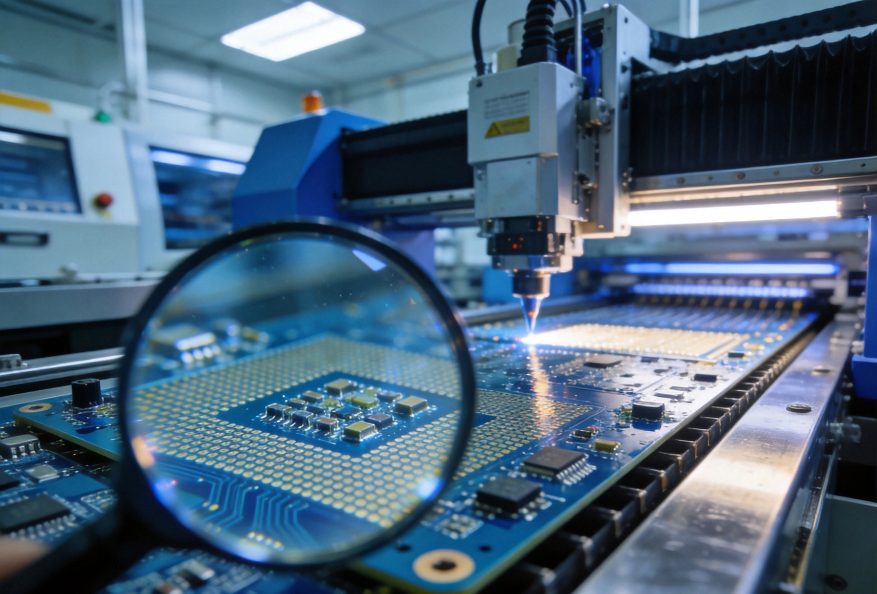
The foundation of every electronic device, a PCB is a laminated structure with conductive copper pathways etched onto a non-conductive substrate. These pathways connect components to form functional circuits. PCBs range from simple single-layer boards with components mounted on one side to complex multilayer assemblies with dozens of conductive layers.
When ordering assembly services, you specify the bare board characteristics along with the components and assembly requirements. The manufacturer needs to understand your board construction to determine appropriate assembly processes and quality standards.
SMT is the dominant assembly method where components are placed directly onto the surface of the PCB rather than inserted through holes. Surface mount devices (SMDs) have small metal terminations or leads that solder to pads on the board surface. This technology enables higher component density, faster assembly, and better high-frequency performance compared to through-hole mounting.
Most modern electronics use almost exclusively SMT components. Understanding SMT helps you appreciate why your board design follows specific rules for pad sizing, component spacing, and thermal management.
THT components have leads that pass through holes drilled in the PCB and are soldered on the opposite side. This mounting method provides stronger mechanical bonds, making THT suitable for components subject to physical stress, high current, or thermal cycling. Connectors, transformers, electrolytic capacitors, and some connectors typically use through-hole construction.
Many assemblies combine SMT and THT components on the same board, called mixed-technology assembly. Your manufacturer needs to know which components use which technology so they can sequence the assembly process correctly.
SMD is the formal term for components designed for surface mount assembly. These parts come in standardized packages with names like 0402, 0603, 0805, QFN, BGA, and SOP. The numbers indicate dimensions in imperial units: an 0603 capacitor measures 0.06 by 0.03 inches.
Smaller packages like 0201 and 01005 enable extreme miniaturization but require precise assembly equipment and stricter design rules. Your manufacturer capabilities dictate which component packages they can reliably assemble.
Gerber files are the universal format for describing PCB manufacturing data. Each layer of your board has a separate Gerber file showing the copper pattern, solder mask openings, silkscreen markings, and drill locations. Your manufacturer uses these files to program imaging equipment and generate manufacturing tooling.
A complete Gerber set typically includes files for each copper layer, solder mask top and bottom, silkscreen top and bottom, board outline, and drill drawing. Ask your manufacturer for their specific Gerber naming convention to ensure files are recognized correctly during CAM processing.
Drill files specify hole positions, sizes, and plating requirements for all holes in the PCB. These files use the Excellon format and include information about which holes should be plated through and which should remain unplated. The drill file tells the drilling equipment exactly where to create each hole and what diameter to use.
Proper drill files are critical for assembly because through-hole component leads must align precisely with the drilled holes. Inconsistencies between drill files and component lead sizes cause assembly problems ranging from poor solder joints to components that simply will not fit.
The BOM lists every component required for your assembly, including part numbers, quantities, reference designators, and sometimes preferred vendors. Reference designators like R1, C5, and U3 identify each component location on the board. Your manufacturer uses the BOM to procure components, verify assembly completeness, and conduct quality checks.
A well-structured BOM includes manufacturer part numbers, not just generic descriptions. This prevents ambiguity when similar components exist from multiple vendors. For turnkey assembly services, the manufacturer sources components based on your BOM, so accuracy directly impacts procurement success.
The pick and place file tells the assembly machine where each component goes on the board and how to orient it. It includes X and Y coordinates for each component center, rotation angle, and component package type. This file comes from your PCB design software and must correspond exactly to your board layout.
Mismatches between the pick and place file and your board revision cause components to land in wrong positions. Always verify that your design files are current and consistent before releasing for assembly.
Solder paste is a sticky mixture of fine solder particles suspended in flux that holds components in place before reflow soldering. It is applied to PCB pads through a stencil using a screen printing process. The paste must have correct viscosity and particle size for the application method and package type being assembled.
Different solder alloys suit different applications. Lead-free tin-silver-copper (SAC) alloys dominate current manufacturing due to environmental regulations, but leaded solders offer lower melting temperatures and better wetting for sensitive components. Your manufacturer selects appropriate paste based on your board contents and reliability requirements.
A stencil is a thin metal sheet, usually stainless steel, with apertures cut to match your PCB pads. It precisely deposits solder paste onto the correct locations during the printing process. Stencil thickness and aperture design significantly affect solder joint quality.
Laser-cut stencils provide the best accuracy for fine-pitch components like 0.4mm pitch BGAs. Electroformed stencils offer superior paste release for very small apertures. Your manufacturer typically fabricates stencils as part of the assembly preparation process.
Reflow soldering melts the solder paste to form electrical and mechanical connections between components and the PCB. The assembly passes through a reflow oven following a carefully controlled temperature profile with distinct zones for preheating, soak, and peak reflow.
The temperature profile must match your board characteristics, component thermal tolerances, and solder paste specifications. Boards with large thermal mass heat differently than small ones, and components near the board edge experience different profiles than those in the center. Professional manufacturers use profiling equipment to optimize profiles for each unique assembly.
Wave soldering is used primarily for through-hole components and bottom-side SMT on double-sided assemblies. The board passes over a standing wave of molten solder that fills holes and contacts component leads. This process provides excellent solder coverage for through-hole joints but subjects all components to thermal stress.
Double-sided assemblies often use different processes for each side: paste and reflow for the top side, then wave soldering for the bottom side after through-hole insertion. Your manufacturer sequences these operations to avoid damaging previously soldered components.
AOI uses cameras and image analysis software to inspect assembled boards for defects. It checks for missing components, misaligned parts, tombstoning, bridging, insufficient solder, and excess solder. AOI provides fast detection of visible defects before functional testing.
While AOI catches many defects, it cannot see hidden problems like insufficient solder inside BGA packages or cold joints that look correct visually. Most professional assembly lines combine AOI with X-ray inspection for comprehensive coverage.
X-ray inspection reveals hidden solder joints beneath components that are opaque to visible light. BGA packages, QFN packages, and other bottom-terminated components require X-ray to verify solder joint quality. The technique works by detecting differences in X-ray absorption between materials like solder, copper, and substrate.
Real-time X-ray shows the actual solder joint structure, while 2D X-ray provides projected images. 3D X-ray tomography offers the most detailed analysis but requires longer inspection time. For high-reliability applications like medical or automotive electronics, X-ray inspection is often specified as a mandatory quality step.
IPC is the global trade association for electronics that publishes industry standards for design, manufacturing, and inspection. IPC-A-610 defines acceptability criteria for electronic assemblies, describing what constitutes acceptable versus defective workmanship. Understanding IPC classes helps you communicate quality requirements to your manufacturer.
IPC Class 3 covers high-performance electronic products where continued performance or on-demand reliability is critical. Class 2 applies to dedicated service electronics. Class 1 covers general electronic products. Specifying the correct IPC class ensures your quality expectations match the manufacturing approach.
DFM is the practice of designing products with manufacturing capabilities and limitations in mind. For PCBs, DFM review examines your design files for potential assembly problems, manufacturing constraints, and cost optimization opportunities. A good DFM review catches issues before tooling begins.
Common DFM findings include component spacing too tight for reliable assembly, traces too narrow for the board house capabilities, via placement under component pads causing solder wicking, and fiducial marks missing from the board. Addressing DFM issues early prevents costly rework or redesign later.
NPI is the process of bringing a new product into manufacturing. It encompasses everything from design finalization through first article approval to production ramp. The NPI phase often reveals design issues, identifies process optimization opportunities, and establishes quality baselines.
Working with your manufacturer during NPI builds mutual understanding of product requirements, manufacturing capabilities, and quality expectations. First article inspection during NPI verifies that the design intent translates correctly into manufactured product.
A first article is a small initial production run used to verify that the manufacturing process produces correct results. The manufacturer inspects the first article against your specifications, identifies any deviations, and implements corrections before full production begins. First article inspection (FAI) documentation provides traceability for what was built and how it compared to requirements.
Do not skip first article approval, even for prototypes. It is far less expensive to discover problems on five boards than to build five thousand before noticing an issue.
Yield is the percentage of boards that pass all quality checks without requiring rework or repair. A 95% yield means 95 out of 100 boards passed inspection on the first attempt. Higher yields indicate better design-manufacturing alignment and lower per-unit cost because rework consumes labor and equipment time.
Typical first-pass yield targets for professional assembly run above 98%. Chronic yield problems usually indicate design issues, component problems, or process drift that requires investigation and correction.
Turnkey assembly means the manufacturer handles everything from bare board procurement through component sourcing, assembly, and sometimes testing. You provide design files and specifications, and the manufacturer delivers finished boards. This model simplifies procurement but requires trusting the manufacturer with component selection.
Turnkey works well when you lack supply chain resources or want single-point accountability. The manufacturer absorbs component procurement risk and must maintain component inventory or sourcing relationships.
In consignment assembly, you provide all components while the manufacturer handles assembly services only. This gives you complete control over component sourcing and often allows using existing inventory. However, you bear responsibility for component availability, shelf life, and consistency between lots.
Consignment requires careful logistics to ensure components arrive at the manufacturer with adequate lead time for kitting and inspection. Component shortages delay your build, so maintain buffer inventory or communicate shortages immediately.
Partial turnkey splits responsibility between you and the manufacturer. You might source specialized components while the manufacturer handles commodity parts, or vice versa. This approach balances control over critical components with the convenience of managed procurement for standard items.
Clear communication about component ownership, incoming inspection procedures, and shortage handling prevents disputes during production. Establish these responsibilities in writing before starting.
Quick turn services prioritize speed over volume pricing, offering faster lead times for smaller quantities. Prototype assembly focuses on validating your design before committing to production volumes. These services typically cost more per board but enable faster iteration cycles.
Use prototyping services to validate design decisions, verify component availability, and establish baseline assembly processes. Moving to production services after prototyping often requires transitioning to different pricing structures and lead times.
MSL classifies components by their sensitivity to moisture absorption and subsequent solder reflow exposure. Moisture trapped inside component packages can vaporize during reflow, causing internal delamination and crack failure. Higher MSL numbers indicate more moisture sensitivity.
MSL-rated components require dry storage and controlled floor life after removal from sealed packaging. Components that exceed their floor life before assembly may require baking to remove absorbed moisture. Your manufacturer tracks MSL requirements and manages component handling accordingly.
BOM alternates are equivalent components from different manufacturers that can replace each other when the preferred part is unavailable. Defining acceptable alternates in your BOM prevents production delays when preferred components go out of stock or experience long lead times.
Not all components have true alternates. Some require specific pinouts, thermal characteristics, or performance specifications that differ between manufacturers. Document alternates clearly and verify compatibility before approving their use.
Different distributors and manufacturers may use different part number formats for the same component. Normalization standardizes these references into consistent internal numbers that match your BOM. This prevents confusion when the same component arrives under multiple part numbers from different sources.
For turnkey assembly, the manufacturer typically handles normalization during component procurement. For consignment, you benefit from normalizing your BOM before submission.
ICT uses bed-of-nails test fixtures to electrically verify individual components and solder joints on the assembled board. It checks for component presence, orientation, value verification, and basic functional connectivity. ICT requires custom test fixtures matched to your board layout.
ICT provides comprehensive defect detection but requires test points added to your design and fixture investment. For high-volume production, ICT fixture cost amortizes across many boards. Low-volume or prototype builds often skip ICT due to fixture expense.
Flying probe testing uses movable test probes instead of fixed fixtures to verify electrical connectivity. It offers faster setup time than ICT because no custom fixture is required, making it suitable for low-to-medium volume production and prototype verification. However, test coverage may be less comprehensive than dedicated ICT fixtures.
Modern flying probe systems achieve reasonable test coverage for most digital and many analog circuits. They cannot match ICT speed for high-volume production but provide cost-effective verification for smaller builds.
FCT verifies that the assembled board performs its intended function rather than just checking individual connections. It applies power and signals to the board and verifies correct outputs and behavior. This test catches issues that component-level testing misses, including timing problems, firmware bugs, and system-level interactions.
Functional test requirements vary widely by product. Some boards require simple power-on verification while others need comprehensive stress testing across environmental conditions. Define your FCT requirements explicitly to ensure appropriate test coverage.
Burn-in testing operates boards at elevated temperature and voltage to accelerate failure of weak components or solder joints. It helps identify infant mortality failures before boards reach customers. This testing is common for aerospace, medical, and other high-reliability applications.
Burn-in adds significant cost and time to production, so it is reserved for applications where field failure is unacceptable or costly. Specify burn-in requirements explicitly since not all manufacturers offer this capability.
ESD protection prevents damage from static electricity during handling, assembly, and shipping. Components and assemblies sensitive to ESD must be handled in protected areas, stored in ESD-safe packaging, and transported in shielded containers. Proper ESD handling protects expensive components from invisible damage that could cause premature field failures.
Verify that your manufacturer follows ANSI/ESD S20.20 or equivalent ESD control standards. Ask about their ESD-protected areas, personnel grounding, packaging materials, and incoming component handling procedures.
Moisture barrier bags protect moisture-sensitive components and assemblies during storage and shipping. These specialized bags prevent moisture ingress that could cause problems during subsequent reflow processing. Humidity indicator cards inside the bags show whether moisture has entered the package.
Bags carry moisture sensitivity level ratings and have shelf life limitations. Always verify bag integrity and humidity indicator status before opening, especially for MSL 3 or higher rated components.
Conformal coating is a protective material applied over assembled boards to protect against moisture, dust, chemicals, and thermal cycling. Common coating types include acrylic, urethane, silicone, and parylene. Each offers different protection characteristics and requires different application and removal methods.
Coating application affects testability and rework since coated boards are harder to probe or repair. Specify coating requirements early since it affects the assembly sequence and may require dedicated equipment.
A centroid file, also called a pick and place file, lists the X/Y position and rotation for each component on your board. This file, usually in CSV or Excel format, tells the assembly machine exactly where to place each part. It must correspond precisely to your Gerber files and component package definitions.
CAD files from your EDA software contain the original design information but require translation into manufacturing formats. Gerber files are the standard manufacturing output that any board house can process. Always provide Gerber files rather than relying on the manufacturer to extract manufacturing data from native CAD formats.
ODB++ and IPC-2581 are intelligent data formats that contain complete manufacturing information in a single structured file. Unlike separate Gerber and drill files, these formats integrate all manufacturing data with validation tools. They reduce file handling errors and enable more sophisticated CAM processing.
Understanding these terms empowers you to communicate clearly with assembly service providers, specify requirements accurately, and evaluate quotes intelligently. When reviewing quotes, ask questions about any terminology you do not understand. Reputable manufacturers welcome informed customers and can explain their processes and recommendations.
As your product matures through prototypes, redesigns, and production ramp, you will encounter additional specialized terms specific to your application and industry. Building relationships with knowledgeable manufacturer representatives accelerates your learning curve and improves outcomes.
Minimum requirements include Gerber files for all board layers, a drill file in Excellon format, a Bill of Materials listing all components, and a pick and place file with component positions. Additional files like the original CAD files, 3D STEP models, and assembly drawings help but are not always required.
Turnkey assembly means the manufacturer sources all components as part of the service. Consignment assembly means you provide the components while the manufacturer handles assembly only. Turnkey simplifies procurement; consignment gives you component control.
IPC-A-610 defines acceptability criteria for electronic assemblies. Specifying IPC Class 2 or Class 3 tells the manufacturer what quality level to target and what defects are acceptable or unacceptable. Class 3 is most stringent and most expensive.
A DFM review examines your design files for manufacturing-related issues including component spacing, pad sizes, fiducial marks, trace routing, via placement, and panelization. The manufacturer identifies potential problems and suggests design changes to improve manufacturability.
Moisture-sensitive components absorb water that can vaporize during reflow soldering, causing internal damage. Proper handling, dry storage, and floor time limits prevent moisture-related failures. Your manufacturer tracks MSL requirements for your components.
Knowing these key terminologies prepares you to navigate PCB assembly services with confidence, whether you are ordering prototypes or scaling to production volumes.
Behind the Scenes: A Tour of Our Advanced SMT Assembly FacilityAugust/07/2026
The Importance of Fiducial Marks and Tooling Holes in PCBAAugust/12/2026

The Role of Low Volume Assembly in Aerospace and DefenseJuly/21/2026

Sustainability in PCB Assembly: Green Manufacturing Practices for the Electronics IndustryJuly/10/2026

Inventory Management Benefits of Using a Turnkey Assembly PartnerAugust/03/2026