Open Nav



Low volume box build assemblies occupy a unique space in electronics manufacturing. They are too complex for simple Turnkey PCB Assembly services, yet the quantities are too small to justify the tooling and automation investments that high-volume production relies on. Custom cable assemblies are a common element in these builds, providing power distribution, signal routing, and inter-board connections within enclosures that house multiple PCBs, sensors, connectors, and electromechanical components. Integrating these cable assemblies effectively requires balancing design intent, manufacturing capability, and cost in ways that differ substantially from either prototype cable work or high-volume cable production. Understanding the challenges and opportunities unique to low volume cable integration helps engineers and project managers navigate this space more successfully.
This article covers the complete process of integrating custom cable assemblies into low volume box builds, from initial design through final assembly and test. Whether you are specifying cable assemblies for a medical instrument, an industrial sensor node, a defense electronics module, or any other low-to-medium volume electro-mechanical product, the principles and practices described here will help you make better decisions and avoid common pitfalls.
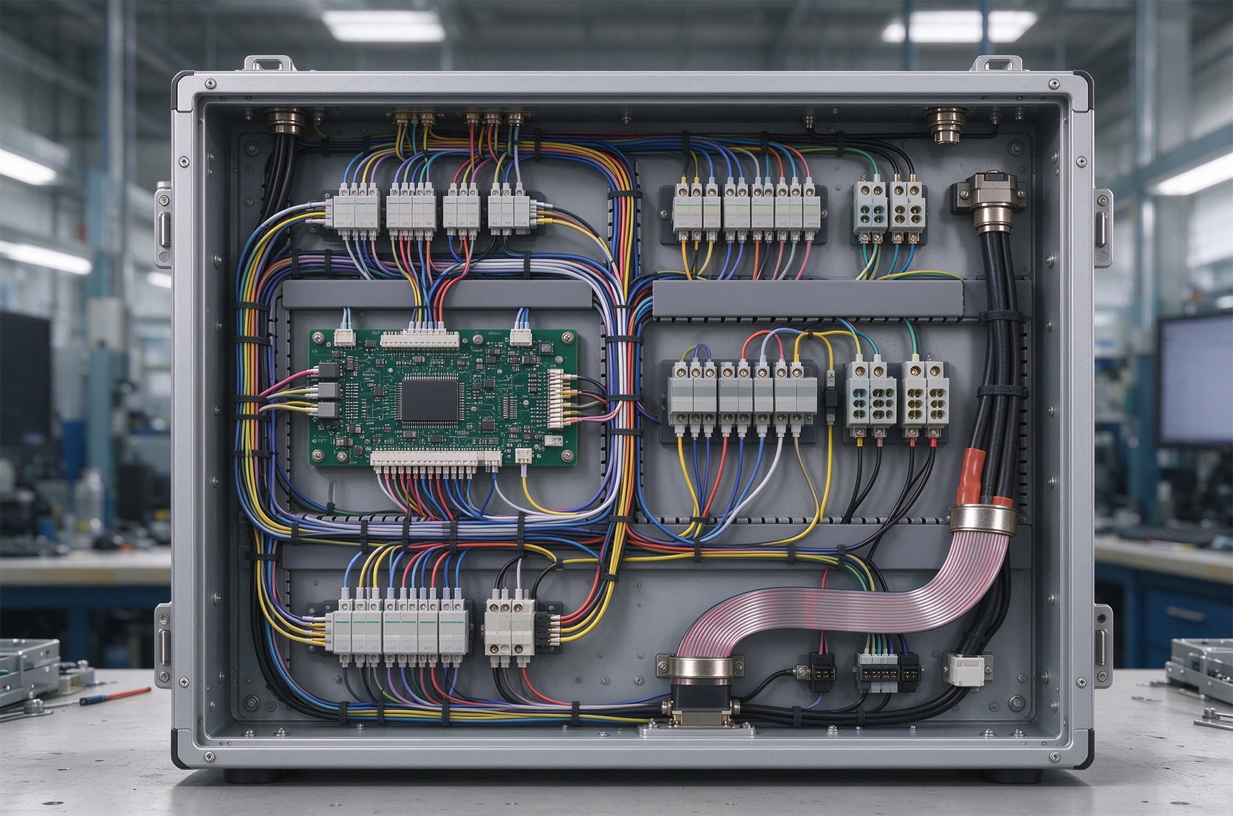
Low volume box builds typically range from a few units to a few hundred units per order. This volume regime is too low for custom injection-molded enclosures, too high for purely hand-soldered prototype assemblies, and too complex for simple single-board PCB assembly services. Box builds involve multiple subassemblies including PCBs, cable assemblies, sheet metal or plastic enclosures, displays, sensors, fans, and connectors, all brought together and tested as a complete system before shipment.
The cable assembly in a box build serves as the nervous system of the product, connecting disparate components within the enclosure and providing external interfaces through panel-mounted connectors. Unlike PCB design where features are precisely defined by photolithography, cable assemblies involve manual or semi-automated termination processes that depend on operator skill, tooling setup, and work instruction clarity. This manufacturing variability is manageable at low volumes but becomes a significant quality risk at higher quantities without appropriate process controls.
Design changes are common during low volume production because the product may still be in refinement. Unlike high-volume production where design changes are avoided at nearly any cost due to tooling amortization, low volume builds can accommodate moderate design evolution between build lots if the cable architecture is planned to accommodate it. Understanding this difference affects how you design the cable system and how you communicate with your manufacturing partner.
Successful cable integration starts with design practices that account for the realities of low volume manufacturing. Cable assemblies designed for manual or semi-automated production have different characteristics than those designed for fully automated high-volume lines, and designing for the wrong production mode leads to quality problems, cost overruns, or both.
Connector selection has an outsized impact on low volume cable assembly success. Connectors that are easy to terminate by hand, with clear visual feedback for correct insertion and robust locking mechanisms, reduce assembly errors and improve reliability. Connectors that require precise crimping force calibration, specialized tooling, or visual access that is difficult to achieve in an enclosed box build are sources of problems at low volumes. Choosing connectors with integral strain relief and polarizing features reduces the dependence on operator skill for these critical functions.
Cable routing should be planned with manufacturing and service access in mind. In a box build, cables must be routed through the enclosure, around other components, and terminated to connectors or boards in a sequence that is achievable without damaging previously assembled components. Designing cable paths with adequate clearance for hand assembly, using cable ties or clips at regular intervals to manage harness shape, and providing service loops for connectors that may need to be disconnected during test or repair all contribute to a more manufacturable design.
Minimize the number of different cable types and lengths in your design. Each unique cable is a separate assembly item that must be fabricated, inspected, and tracked through the build process. Consolidating to fewer cable types with standardized lengths simplifies inventory management and reduces the opportunity for mix-ups during assembly. If your design naturally uses several different cable lengths, consider whether a modular approach with adapter cables or connectorized sub-harnesses could reduce the number of unique cable part numbers.
The termination method used to attach wires to connectors or boards determines the mechanical reliability, electrical performance, and manufacturing cost of the cable assembly. Each termination type has characteristics that make it more or less suitable for specific applications, and the choice should be made deliberately rather than defaulting to familiar methods.
Crimp terminations are the most common method for low volume cable assemblies because they are fast, reliable when done correctly, and require relatively simple tooling. The basic crimp tool, often called an EIA tool, can be used by operators with minimal training to produce consistent terminations. The critical factor is using the correct die for the specific terminal and wire combination, and verifying that the crimp meets the visual and pull-force criteria defined by the applicable standard, typically MIL-T-22520 or equivalent. Pre-insulated terminals with color-coded insulation grip sleeves are particularly suitable for low volume work because they provide visual confirmation of correct insertion depth.
Solder terminations provide superior mechanical and electrical joint quality when performed correctly, but they are slower and more dependent on operator skill than crimp terminations. Solder joints are susceptible to cold joints, disturbed joints, and insufficient wetting if the operator is not properly trained or the work environment is not controlled. For low volume production where speed is less critical than reliability, solder terminations may be appropriate for critical signal connections or for connectors that do not have reliable crimp options.
Insulation displacement contact termination, sometimes called IDC or poke-home termination, allows wires to be inserted without stripping, with the termination made by the IDC blade cutting through the insulation to make contact with the conductor. This method is fast and eliminates the need for stripping and crimping operations, but it requires specific wire gauges and types compatible with the IDC design, and the termination quality is sensitive to wire strand count and insulation thickness variation.
The physical fabrication of cable harnesses for low volume box builds involves cutting wires to length, stripping insulation, terminating to connectors or contacts, bundling and routing the harness, and applying strain relief and identification markers. Each step needs to be documented clearly enough that operators can produce consistent results and inspectors can verify that the harness meets specifications.
Create a complete wire list that specifies every wire in the assembly including signal name, wire gauge, insulation type, color code, origin connector and contact, destination connector and contact, and any special instructions. This wire list is the authoritative reference for harness fabrication and must be kept synchronized with any design changes. Many engineers maintain wire lists in spreadsheet format, but purpose-built harness documentation software provides better validation and traceability for complex harnesses.
Harness drawings should show the physical arrangement of the harness including connector positions, cable routing paths, tie-down locations, and any special routing requirements like minimum bend radius or clearance from heat sources. Three-dimensional models from CAD software can be used to generate harness drawings that accurately reflect the physical arrangement, but these should be verified against physical prototypes because cable routing does not always behave as the CAD model predicts. A simple hand-drawn sketch with dimensions and notes is often sufficient for simple harnesses and may be faster to produce than a formal CAD drawing.
Identification markers applied to cables and connectors at designated positions enable assembly, test, and service personnel to trace connections quickly and correctly. Wire markers at regular intervals along the harness, numbered to match the wire list, are essential for complex harnesses where many wires are bundled together. Connector identification labels that match the wire list terminology prevent confusion when multiple connectors of the same type are present in the assembly.
The cable harness does not exist in isolation within a box build. It must be integrated with the assembly of other components, and the sequence in which subassemblies are installed affects both the accessibility for cable termination and the risk of damage to previously installed components. Planning the assembly sequence thoughtfully prevents rework and quality problems.
Typical low volume box build assembly sequences start with the mechanical sub-assembly, installing standoffs, guides, and mounting hardware in the enclosure. PCBs are installed next, secured to standoffs and connected to panel components through temporary or permanent wiring. The cable harness is often installed as a sub-assembly before final enclosure closure, with connectors mated and strain relief applied before the enclosure is closed. Final steps include installing covers, performing system-level testing, and applying any required calibration or configuration.
Some cables must be routed and terminated after other components are already in place, which requires designing for access. If a PCB must be installed before its board-to-board cable can be terminated, the connector must be accessible from the side or top of the board after it is secured. Designing connectors with adequate clearance and ensuring that cable routing does not require reaching into confined spaces behind already-installed components reduces assembly difficulty and error rates.
Service loop planning is particularly important in box builds where cables may need to be disconnected during test, debug, or repair activities. Providing enough extra cable length to allow connectors to be reached and mated without tension or binding enables these activities without requiring disassembly of other components. The service loop requirement must be balanced against the risk of excess cable causing interference or preventing proper enclosure closure.
Testing cable assemblies in low volume box builds serves multiple purposes: verifying correct wiring, identifying assembly defects before they become system failures, and providing documentation that the assembly meets specifications. The testing approach should be scaled to the complexity and criticality of the specific product.
Continuity testing verifies that each wire in the harness is connected from the correct origin to the correct destination, with no opens, shorts, or mis-wires. For simple harnesses with a dozen or fewer connections, a simple multimeter may be sufficient. For complex harnesses with dozens of connections, a dedicated cable harness tester with automated test sequencing provides faster and more reliable verification. Some harness testers can verify the harness against the wire list automatically, generating a pass or fail result and a list of any discrepancies found.
Hi-pot testing, which applies a high voltage between circuits to verify adequate insulation resistance, is appropriate for harnesses that will carry AC line voltage or high-voltage power supply rails. This test identifies insulation defects that could create safety hazards or reliability failures. The test voltage and pass criteria should be specified based on the applicable safety standards for the product, typically determined by the maximum voltage present in the harness.
Functional testing of the completed box build, beyond simple continuity verification, validates that the cable assembly works correctly within the system. This may include verifying power distribution to all boards, checking communication paths between components, and confirming that sensor readings or actuator responses are correct when the cable harness is properly connected. Functional test procedures should be documented and repeated for every unit produced to ensure consistent quality across the production run.
Many companies source custom cable assemblies from specialized service providers rather than manufacturing them in-house. Choosing the right service provider and managing the relationship effectively affects cost, quality, and delivery reliability for low volume box builds.
Evaluate service providers on their experience with your specific cable types and termination methods, not just their general cable assembly capability. A provider with extensive experience in automotive cable harnesses may not be the best fit for a low-volume medical device assembly, and vice versa. Ask about the industries they serve, the typical volumes they handle, and the quality systems they have in place. ISO 9001 certification provides a baseline quality management expectation, while industry-specific certifications like AS9100 for aerospace or IATF 16949 for automotive indicate deeper quality system maturity in those domains.
Communication of requirements should be clear and complete before production begins. Provide the service provider with complete wire lists, harness drawings, connector specifications, and any special instructions for your application. Request a pre-production sample for first article inspection, where you can verify that the harness meets your specifications before the full production run begins. This investment in first article review catches specification misunderstandings early, before they multiply across the production quantity.
Expect the cost structure for low volume cable assemblies to reflect the manual work content involved. Cable termination is largely a manual process that does not benefit from the economies of scale that reduce per-unit costs at higher volumes. Setup costs for tooling, documentation preparation, and first article inspection are amortized across smaller quantities, leading to higher per-unit costs. Understanding this cost structure helps you evaluate quotes realistically and identify when in-house cable assembly might be more economical for your specific volume range.
Cost management in low volume cable integration involves balancing material costs, labor costs, and the overhead of managing cable assembly as a distinct manufacturing activity. Several strategies can reduce total cost without sacrificing quality or reliability.
Standardize connectors and cable types across products where possible. Using the same connectors across multiple products reduces the variety of special tooling required, simplifies inventory management, and allows operators to develop proficiency with specific connector types rather than constantly re-learning new ones. Even within a single product, minimizing the variety of connectors and cable sizes reduces setup complexity and improves consistency.
Consider semi-automated termination equipment for production runs that are too large for purely manual assembly but too small for fully automated lines. Bench-top crimp presses with programmable force control, automatic wire cutting and stripping machines, and semi-automatic termination equipment can increase throughput and consistency for repetitive operations while remaining economical at low volumes. The equipment investment is modest compared to high-volume automated lines, and the productivity improvement often pays back quickly in reduced labor cost.
Pre-fabricate cable sub-assemblies as separate work orders before they are needed in the box build, rather than waiting to build them as part of the system assembly. Pre-fabricated sub-assemblies can be built in parallel with other system activities, reducing the total build cycle time and allowing defects to be identified and corrected before the sub-assembly is needed in the system. This parallel processing approach is particularly valuable when the cable assembly has long lead times or high defect rates that would otherwise delay the overall build.
Custom cable assembly integration in low volume box builds requires a different approach than either prototype cable work or high-volume harness production. Success depends on designing for manufacturability, choosing appropriate termination methods, creating clear documentation, planning the assembly sequence to accommodate cable installation, implementing appropriate testing, and managing the relationship with your cable assembly service provider effectively.
The cable harness is often treated as a commodity add-on, but it deserves the same engineering attention given to PCB design and enclosure mechanical design. A well-designed cable harness contributes to system reliability, manufacturability, and serviceability, while a poorly designed one creates quality problems, assembly delays, and field failures that are expensive to diagnose and repair. Investing the effort to do it right pays dividends across the entire lifecycle of the product.
Contact us to discuss your requirements and explore how custom cable assembly integration can support your low volume box build needs.
Streamlining Production with Integrated PCB Fabrication and AssemblyJuly/20/2026
The Role of SPI (Solder Paste Inspection) in Reducing SMT DefectsSeptember/08/2026
The Hidden Costs of DIY PCB Assembly vs. Professional ServicesAugust/11/2026
Offshore vs. Domestic PCB Assembly Services: Analyzing the Trade-offsJuly/16/2026

Supply Chain Resilience: How Turnkey Providers Handle ShortagesSeptember/28/2026